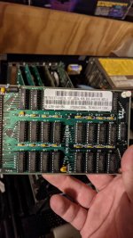
I managed to get an original NOS EGA expansion card from a friendly chap who had scored some from Computer Reset. Thought I might chime in to help with whatever info I can add.
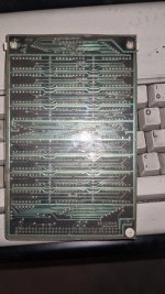
The male pin headers are approximately 0.4" / 1cm tall, from the PCB surface to the tip of the pins. That's about 0.3" / 8mm of actual mating surface, with the height of the plastic shroud consuming the ~0.1" remainder. It's a 64-pin header in 2x32 arrangement. When you're looking at the component side of the card, with the header along the right edge of the card, pin 1 is the top right corner. Odd pins on the right side, even pins on the left.
FWIW, my expansion card came with a plastic guide installed over the pin header. It looked, at first, like a female-to-female coupler, but there are no contacts in it -- just plastic. Might just be there to protect the pins from getting bent in shipping. (Nice touch!)
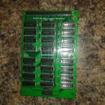
The standoffs have a 1/2" board-to-board spacing. That is, if you snapped the expansion card on to the EGA card, it would be 1/2" between the PCB surfaces. The expansion card holes are roughly 4.65mm in diameter, give or take a bit due to measurement error. My calipers say the neck of the standoff (where it rests in the PCB when installed) is about 3.6mm. NOTE: The EGA card side of the standoff is smaller in diameter.
Best I can tell, the standoff holes are 3.5" C-to-C on the left side of the board, and it looks like 5.6" from the standoff center to the center of Pin 1 of the header. Pin 1 center is about 0.3" from the top board edge, and the opposite side stand-off center is about 0.2" from the top board edge.
Board size is roughly 6.125" x 3.9". That ought to be enough of the critical dimensions to help anyone designing their own, or modifying a design for the best fit.
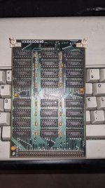
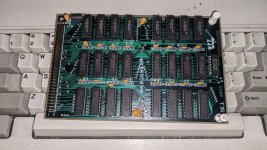
Now a question -- mine looks to have been reworked quite a bit. Seems factory. My board is stamped "6480099XM".
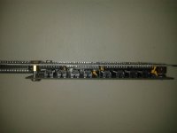
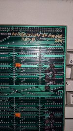
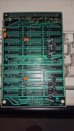
In addition to the typical yellow 10u/16v tantalum caps at C17, C18, and C19, there are three additional tantalum caps on the back side of the board -- one bodged in on the rails running down around dead center of each "bank" on the left and right sides of the board, and one on the bottom left (looking at the solder side, header on left.) They are labeled "15-20" and orange in color.
There are a couple 100n ceramic caps on the bottom left, and a whole cluster of 15p black film(?) caps on the top of each bank, soldered to the chip pins.
It also appears the positive rail has been cut, where it runs from the pin header to the bottom edge of the board. A ferrite choke has been installed in-line between the two new ceramic caps.
Anyone seen this before?


")