• Please review our updated Terms and Rules here

PET 2001 Booting Issues

Err, there isn't a pin 41 on the CPU - it is a 40 pin device...

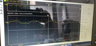
You must be able to move channel #1 to the middle of the screen and select 2V/div or or further down and select 1V/div to get a better view of the waveform.

Exactly which pin are you measuring though?

Dave
 
No voltage check yet still have to pickup a 9v battery. I did calibrate the scope and the waveform looks nice and square.
You can measure voltages and ripple with your scope as well, the digital ones output the numbers too
 
Err, there isn't a pin 41 on the CPU - it is a 40 pin device...

You must be able to move channel #1 to the middle of the screen and select 2V/div or or further down and select 1V/div to get a better view of the waveform.

Exactly which pin are you measuring though?

Dave
Hey Dave

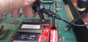
This is the pin I am scanning and this is the output on the screen.

285731211_563687575216714_5490944252016292879_n.jpg
289824427_556466389406805_7063778343095551556_n.jpg
 
You are measuring address line A8 there (pin 17) not a clock.

The pins are numbered in an anticlockwise direction around the chip with pin 1 to the LEFT of the notch on the IC.

You should be measuring pin 37 (for the input clock) and this is on the diagonally-opposite side of where you are measuring in the photograph.

See the datasheet or https://en.wikipedia.org/wiki/File:MOS6502.svg for details.

Dave
Hey Dave

That makes sense, thanks for the pin out reference I was looking for one of those yesterday I made a video to show whats going on when I scope pin 37.


Thanks

Cheers,
Ryan
 
Also I am getting 4.95-5.10 volts coming from the large capacitor to the mains on the board so I am guessing that is within normal specification?
Hmm,

If you have measured the voltage across the large capacitor external to the mainboard then it should be more like 9V (unregulated) rather than 5V...

4.95V to 5.10V looks fine for the dc component of the 5V rail - however, there are usually multiple 5V regulators (depending upon the type of PET). There may be other voltages to check as well (again, depending upon the type of PET).

You should also be using your oscilloscope (set to AC coupling) to view the noise on the supply rail. Keep increasing the sensitivity of the oscilloscope channel until you observe some noise - it must exists! Measure the high and low value of the noise. You will also need to sweep the timebase to see any main-based noise (faulty bridge rectifiers or smoothing capacitors) at a frequency of 50/60/100/120 Hz and induced noise as a result of faulty decoupling capacitors and IC switching. This noise will be quite high frequency.

Dave
Hey Dave

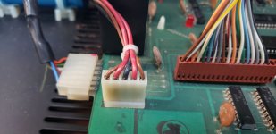
I will try those things, did you happen to watch the video I posted? Also it does seem like there should be 9v coming off that capacitor, I measured at this connector the back of each pin and I was getting 4.95-5.10 on the live wires and proper ground on the grounds.

Thoughts?

285875658_1054159991971699_8525837363393746784_n.jpg
 
Pins 1 and 5 of J8 (brown wires) should come from the transformer.

Pin 3 of J8 (black wire) should come from the centre-tap of the transformer and the negative side of the capacitor.

Pins 2 and 4 of J8 (red wires) should go the positive side of the capacitor.

You should measure at least 7.5V across the capacitor. This then feeds the input of four (4) +5V regulators on the board.

If the DC level is low going into the regulators - you can forget taking any more measurements until this is fixed. Yes, I did watch the video.

Remove J8 from the main logic board (to prevent loading up the transformer).

With your multimeter set to AC volts (say 12V or so full scale) measure the voltage between the following pins of J8 (on the cables not the PCB):

Each of the brown wires in turn to the black wire.

Between the two brown wires.

Post the results back.

Don't reconnect J8 just yet.

Next, we need to check if the two rectifier diodes (CR1 and CR2) are healthy. They should conduct in one direction but not the other when tested with the diode test position of your multimeter (assuming you have such a setting of course).

Then we need to check out the large, blue capacitor next...

Dave
 
Pins 1 and 5 of J8 (brown wires) should come from the transformer.

Pin 3 of J8 (black wire) should come from the centre-tap of the transformer and the negative side of the capacitor.

Pins 2 and 4 of J8 (red wires) should go the positive side of the capacitor.

You should measure at least 7.5V across the capacitor. This then feeds the input of four (4) +5V regulators on the board.

If the DC level is low going into the regulators - you can forget taking any more measurements until this is fixed. Yes, I did watch the video.

Remove J8 from the main logic board (to prevent loading up the transformer).

With your multimeter set to AC volts (say 12V or so full scale) measure the voltage between the following pins of J8 (on the cables not the PCB):

Each of the brown wires in turn to the black wire.

Between the two brown wires.

Post the results back.

Dave
Hey Dave

Will do, I am seeing 5ish volts off the posts of the capacitor....what are the options for replacement power supplies these days? I feel like that tech has come a long way since 1977 haha.
 
Pins 1 and 5 of J8 (brown wires) should come from the transformer.

Pin 3 of J8 (black wire) should come from the centre-tap of the transformer and the negative side of the capacitor.

Pins 2 and 4 of J8 (red wires) should go the positive side of the capacitor.

You should measure at least 7.5V across the capacitor. This then feeds the input of four (4) +5V regulators on the board.

If the DC level is low going into the regulators - you can forget taking any more measurements until this is fixed. Yes, I did watch the video.

Remove J8 from the main logic board (to prevent loading up the transformer).

With your multimeter set to AC volts (say 12V or so full scale) measure the voltage between the following pins of J8 (on the cables not the PCB):

Each of the brown wires in turn to the black wire.

Between the two brown wires.

Post the results back.

Don't reconnect J8 just yet.

Next, we need to check if the two rectifier diodes (CR1 and CR2) are healthy. They should conduct in one direction but not the other when tested with the diode test position of your multimeter (assuming you have such a setting of course).

Then we need to check out the large, blue capacitor next...

Dave
Also I assume the brown leads from the transformer are grounds is that correct?
 
Had to help someone out from Church with their PC...

You have a transformer and a capacitor external to the PET logic board - and that's it. You can provide an external +5V DC supply - but then you have to start to remove the on-board voltage regulators and other things for it to work properly...

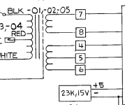
There is no such thing as a 'ground' on the secondary side of these transformers. This is the schematic for the 8032 transformer and capacitor. Please ignore the numbering - it is not applicable to your machine! But I have left it their for me to reference within the text of my post.

1656603876430.png

Pins 4 and 6 (in this example) will be your brown wires and pin 5 will be your black wire.

The black wire is the centre-tap of the winding and the two brown wires are each end of the winding. Neither are connected to ground (directly) (i.e. the transformer secondaries are floating. The other winding is for the monitor.

Dave
 
Usually (check your schematic!) the wires coming out of the secondary transformer windings are not ground but AC live and neutral. There is a third safety earth connection which grounds the metal case, and in case of the PET the DC ground is referenced to earth ground (at least in mine, where a black wire was connected to the post in the back of the case together with the earth ground one). With an earth ground referenced circuit shouldn't connect your scope's ground lead to anything else than ground to avoid a short.
 
Live and neutral generally refer to the transformer primary connection to the incoming mains.

There is no live and neutral on the secondary side of a transformer (in general).

Dave
 
They are just a centre-tapped, floating secondary transformer winding.

On the 'mains' side of the supply, the neutral cable is generally bonded to earth somewhere - be that in the premises or back at the sub-station etc. - whilst the live isn't. You can still build up a (small) voltage differential between neutral and earth as well - depending upon where the neutral is bonded to earth of course.

In the case of the PET, the centre-tap effectively becomes the 0V rail of the power supply which is (in turn) connected to the case which is (in turn) bonded to the safety earth. So, in effect, the black wire of the transformer secondary (centre-tap) becomes the earth potential and the two brown wires are (effectively) referenced to it. But once J8 is removed, no such connection exists anymore.

Dave
 
Back
Top