• Please review our updated Terms and Rules here

IBM 5151 Mono Monitor Partially Working?

seaken

Veteran Member
Joined
Jun 20, 2016
Messages
577
Location
Shokan, New York
I have had this IBM Model 5151 monitor for several years. I don't think I got it with an IBM system, it was on it's own.

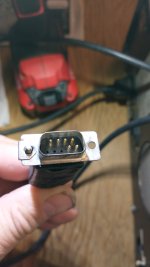
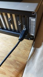
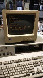
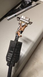
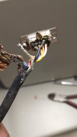
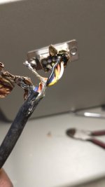
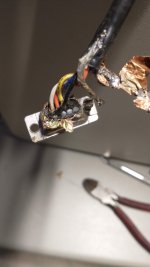
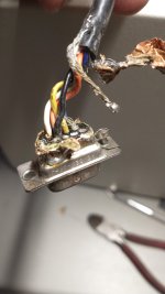
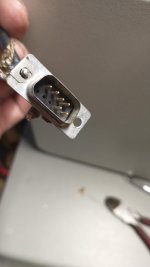
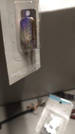
It seems to be partially working, in that I get some green display when I turn the brightness knob up. But when I boot the PC it does not display any characters. The end of the signal cable has been manually doctored by someone before I got it. Maybe it is disconnected inside the 9-pin connector?

I double-checked that the Mono Display Adapter is working by hooking up another mono monitor. It works. So the problem is definitely with the 5151.

How do I go about troubleshooting this monitor. What is needed to display text on the display. Is it just a single line in the cable? Or is it likely to be something inside the monitor that needs attention?

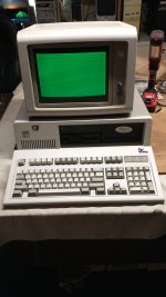
As you can tell, I have very little knowledge about what makes these things work, in spite of watching lots of video of others troubleshooting CRT monitors. I wish I could find a video that shows how to troubleshoot a Model 5151. But the one that I found did not need any repair to the monitor, it just needed to be cleaned and it worked. I would love to get this monitor to work so I could put it on display with my 5162 to get a very traditional PC look.

Here's some photos showing the end of the cable and the green light on the screen at boot, and compared to a working monitor at boot.

Any ideas?

Seaken
 

Attachments

  • IMG_20220905_194345208.jpg
    IMG_20220905_194345208.jpg
    841.6 KB · Views: 10
  • IMG_20220905_194407171.jpg
    IMG_20220905_194407171.jpg
    566.2 KB · Views: 13
  • IMG_20220905_194445626.jpg
    IMG_20220905_194445626.jpg
    873.5 KB · Views: 15
  • IMG_20220905_200023936.jpg
    IMG_20220905_200023936.jpg
    937.2 KB · Views: 18
  • IMG_20220905_203843166.jpg
    IMG_20220905_203843166.jpg
    859.2 KB · Views: 17
Given the condition of the plug from the monitor, I suspect you're correct in someone having "doctored" the connections---possibly trying (and failing) at getting it working. Likely you'd find something on modem7's site (or perhaps he'll be along shortly with assistance).
 
I read a couple of things on minuszero but I didn't understand it. I think I need a crash course in video output circuitry!

Maybe I can just open that connector and see about making sure the wires and pins are properly connected. But I'll need some guidance on what wires need to go to what pins. I saw there are six pins used and two are grounds. That's all I know so far.

Seaken
 
Ahh, got some clues here:

minuszerodegrees.net
I'll try to check these out next weekend.
Because you have a stable raster showing, the relevant section on the web page is the section named 'SYMPTOM: No video, but a stable raster shows if brightness turned up'.

So the first thing to try is to turn down the brightness control, and then turn up the contrast control.

Good to have the problem identified as being the 5151. If the aforementioned action does not reveal video, then it becomes a case of working out where the video signal from the (known good) video card is getting 'lost'. As T-R-A implied, the electrical tape about the 5151's DE-9 plug is suspicious. You need to remove the tape then inspect. You may find that the wire has come away from pin 7 of the plug (pin 7 carries the video signal).

In the photo at [here], the pin 7 wire is orange, but it could be a different colour in your 5151.
 
Also wouldn't hurt to ohm-out the connections from the D-connector back to the monitor, even if you find the connector to be correct. If there's a ground shield inside the cable (don't know, since I don't have a 5151), it would also benefit to make sure one of the "data" lines isn't shorting to it as well.
 
I opened the end of the connector and I think it's safe to say that it was a poor attempt by the previous owner to repair the connections. I'm not great at soldering but this is a real cob job and I know I can do better.

I scrounged through my drawers and found a solder type 9-pin connector and a clamp on hood. I used to make serial cables many years ago and I think this will be similar.

I only need to identify the pin numbers. It think I can figure that out from this damaged connector and the pictures on minuszerodegrees.net.

I'm fairly confident I can solder the correct wires to the connector. But I am not quite sure how to handle the shielding for the cable. It looks like the last guy also had trouble figuring that out and made a mess. Can I just wrap it with foil after I solder it and then place it into the hood? I don't think I need to make a positive connection to the shielding, right?

Also, there is only one black ground wire coming out of the cable. Should I be soldering that single ground wire to both pins 1 and 2?

Thanks for any tips you can offer before I attempt the repair. Here's some pics of the botched wiring and connector that was under that wrap of electrical tape.

Seaken
 

Attachments

  • IMG_20220906_183246102.jpg
    IMG_20220906_183246102.jpg
    500.2 KB · Views: 11
  • IMG_20220906_183836460.jpg
    IMG_20220906_183836460.jpg
    479 KB · Views: 10
  • IMG_20220906_183836493.jpg
    IMG_20220906_183836493.jpg
    461.4 KB · Views: 11
  • IMG_20220906_183902061.jpg
    IMG_20220906_183902061.jpg
    481.2 KB · Views: 12
  • IMG_20220906_183906706.jpg
    IMG_20220906_183906706.jpg
    533.6 KB · Views: 9
  • IMG_20220906_183915306.jpg
    IMG_20220906_183915306.jpg
    336.6 KB · Views: 8
  • IMG_20220906_184703848.jpg
    IMG_20220906_184703848.jpg
    952.7 KB · Views: 6
  • IMG_20220906_184715157.jpg
    IMG_20220906_184715157.jpg
    385.4 KB · Views: 7
  • IMG_20220906_184721526.jpg
    IMG_20220906_184721526.jpg
    459.4 KB · Views: 9
Ahh, that explains why the solder was all over the connector and why they had connected some of the shielding to the body of the connector. If I use a wrap of foil I should be able to flow some solder over the wrap and onto the body of the connector. Does that sound about right?

Seaken
 
In the picture here


it seems there is only one black wire connected to pin 2 and it appears that the braided shielding is connected to Pin 1. Do I have that right?

When I look at the cable end on the Leading Edge monitor it only has a pin at Pin 2. Pin 1 is missing. So I am thinking I only need to attach the black ground wire to Pin 2. Correct?

Also which pin is 6? The white or blue? (Oh, I re-read what modem7 wrote that pin 7 is orange. So, pin 6 is white. Right?)

Seaken
 
Last edited:
It really doesn' t matter--the shield is mostly for FCC Part 15 compliance--radio interference. You can leave the shield unconnected.
Chuck (G) is correct. It's not absolutely necessary to connect the shield. As long as none of the other lines are shorted to it, it'll be fine. IBM "overbuilt" the early systems; thus the reason they are considered "built like a tank". The Part 15 compliance involves just about anything in the RF range, but sometimes it's overkill.
 
It looks like the blue wire was mangled and maybe had some of the shielding touching it. That is pin 9, Vertical Sync. Would that cause no video in the same way as a bad Pin 7? Pin 8, yellow, is enough for the raster to show? Or it needs both pins 8 and 9 for the raster?

Seaken
 
Now that you have the requisite information to reconstruct the connector, why indulge in further speculation? Just fix it and plug it in :D
 
I plan on getting to the soldering on Sunday. But I'm trying to learn. That does sometimes require speculation and asking questions. I even think about the possibilites while I am driving!

I am curious as to why the pin 7 seems well connected but pin 9 seems bad. I was wondering if having a bad pin 9 can exhibit similar results as a bad pin 7. Remember, I have no experience yet and maybe someone else does and knows the answer to my speculative query.

Seaken
 
Personally, if you suspect any dodgy connections, they probably need to be addressed. If anything is happening near the D-connector end, then invest in a good pair of wire strippers, cut the connector off and strip back everything a few fractions (say 1/2") beyond the fault and use the new connector you found to recreate. If there's something mid-cable, then a patch-job may be necessary. Practice some with some junk wiring if you're not terribly experienced with this....in reality it's not that difficult.
 
Back
Top