gwiley
Experienced Member
First step was to remove the power supply, disconnect and/or remove the 3 large electrolytic capacitors and reform them.
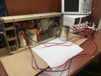
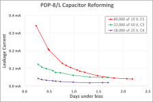
The reforming jig is very similar to the one used for reforming electrolytics in the PDP-8/M.
PDP-8/M supply reforming with schematic:
https://forum.vcfed.org/index.php?t...-new-old-pdp-8-m-chassis.1238187/post-1256186
Next, test the 5V regulator with it disconnected from the bridge rectifier and input filter cap. I wasn’t able to find requirements for output current of the 5V regulator, so a load test was performed using a Kunkin electronic load. The output current was gradually increased while using my finger to monitor the temperature of the 2N3055 pass transistor.

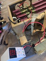
I was a bit nervous to do the following without having checked any of the modules but with the 5V regulator disconnected from the backplane, I connected a lab supply set to output 5 volts to the backplane through a spare G785 board. The 5V current consumption was measured with probably nothing running. Here’s the photo; it draws about 5.1 A so testing the regulator up to almost 9 A might be sufficient.
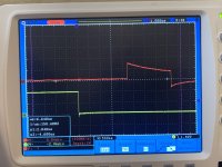
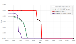
Previously I saw Roland’s github repository containing files that describe an additional 5 volt crowbar/OVP for the 8/L. https://github.com/Roland-Huisman/Crowbar_PDP8-L It mentions a situation where the regulator output voltage can spike above 5 volts while the voltage is ramping up. I was curious about this so I performed a Vin vs. Vout test to observe the problem. As expected, mine does the same thing.

Additionally, the 8/L’s crowbar/OVP uses the same voltage reference as the regulator, so that could fail and cause the output voltage to be too high and not trip the crowbar. So, I built and tested 2 copies of Roland’s crowbar OVP and performed a test to determine the trip point:
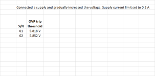
I might set the threshold a tiny bit higher so it’s not prone to trip when the 5V supply ramps up. Notice in the chart above that my supply goes to 6.043 volts before in snaps back to 5 volts.
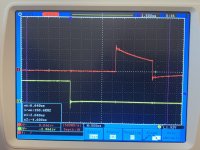
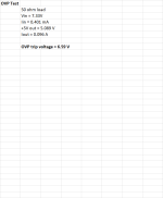
Here are the test results of the 8/L’s native crowbar/OVP:
None of the other supply voltage outputs have been tested yet because the 8/L power supply has not yet been plugged into a 120 VAC wall socket. It’s probably about time for this to happen but with the supply connected to loads first, not connected to the backplane.
Made some progress on the Stearns Flip Chip tester so it was time to start testing some of the simple M-series modules in the 8/L. This is pretty much all of the modules toward the front panel that are in front of the G-series modules. I’m quite fortunate to have a tester based on an existing tester design and have access to a nice library of tests which makes this process *much* easier. When a module is good it gets a yellow dot sticker. When a module tested bad it was replaced with one of the spares (which were also tested in the tester) and that module would get a yellow dot sticker with a small circle in the middle. In a couple of cases the original module was repaired on the spot so it got a yellow sticker with a dot or an R. Here’s a photo of the card cage with stickers on the modules. 11 modules tested bad so far, 2 were repaired and 9 were swapped from the spares kit. Before each module was tested it got a good cleaning which was actually the most time-consuming part of the process.
The M700 in slots C2+D2 is missing in the photo because it was in the tester when the photo was taken. There are still more modules to test and I expect to find more bad parts.
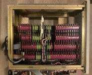
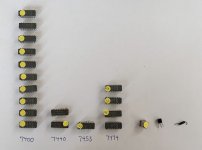
Here’s a tally of what was bad (so far):
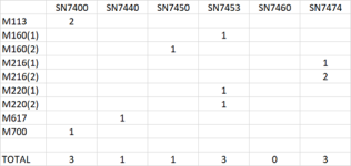
(The first row indicates that there were two bad SN7400’s on one M113 module.)
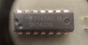
In addition to the above, there was an M113 with a bad via/feed-through that was fixed by resoldering it. An M310 delay line module had a bad Q1 PNP transistor. I replaced it with a 2N3906 because this transistor seems to be nothing special in this circuit. The M310 worked properly after replacing Q1. I have parts on order to repair the rest of the above modules. Some have arrived already.
(I used to have a big pile of SN7400 chips but gave them away a few years ago thinking: “when am I ever going to use these?”. Ha! If I had only known I’d have a renewed interest in the PDP-8. I’ll have to share my story about the PDP-8 sometime and building a morph between a PDP-8 and Nova.)
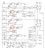
Spent a little time with the M700 Manual Timing Generator. E3, a 7400, is almost certainly bad. I can swap that tomorrow. For now, I’m using the M700 from the spares kit so I’ll be able to run the updated M700 tests and be able to evaluate the pulse filter circuit and the pulse chain generator that generates MFTP0, MFTP1 and MFTP2.
Given that so many bad modules have been found so far, I’d really prefer to test as many as possible in the tester before powering up the whole unit to see what works and what doesn’t. I’m kind of surprised to see so many bad chips because Omnibus modules that I’ve purchased from various sources have rarely had bad chips. The date codes of chips in the 8/L are a bit older though. Maybe IC passivation, and just chip manufacturing process and quality control improved a lot over the few years between the 8/L and 8/E,F,M. Looking through the forum I see that others have had similar experiences with many bad components in their 8/L.
I hope to have more to share soon…


The reforming jig is very similar to the one used for reforming electrolytics in the PDP-8/M.
PDP-8/M supply reforming with schematic:
https://forum.vcfed.org/index.php?t...-new-old-pdp-8-m-chassis.1238187/post-1256186
Next, test the 5V regulator with it disconnected from the bridge rectifier and input filter cap. I wasn’t able to find requirements for output current of the 5V regulator, so a load test was performed using a Kunkin electronic load. The output current was gradually increased while using my finger to monitor the temperature of the 2N3055 pass transistor.

I was a bit nervous to do the following without having checked any of the modules but with the 5V regulator disconnected from the backplane, I connected a lab supply set to output 5 volts to the backplane through a spare G785 board. The 5V current consumption was measured with probably nothing running. Here’s the photo; it draws about 5.1 A so testing the regulator up to almost 9 A might be sufficient.

Previously I saw Roland’s github repository containing files that describe an additional 5 volt crowbar/OVP for the 8/L. https://github.com/Roland-Huisman/Crowbar_PDP8-L It mentions a situation where the regulator output voltage can spike above 5 volts while the voltage is ramping up. I was curious about this so I performed a Vin vs. Vout test to observe the problem. As expected, mine does the same thing.

Additionally, the 8/L’s crowbar/OVP uses the same voltage reference as the regulator, so that could fail and cause the output voltage to be too high and not trip the crowbar. So, I built and tested 2 copies of Roland’s crowbar OVP and performed a test to determine the trip point:

I might set the threshold a tiny bit higher so it’s not prone to trip when the 5V supply ramps up. Notice in the chart above that my supply goes to 6.043 volts before in snaps back to 5 volts.
Here are the test results of the 8/L’s native crowbar/OVP:

None of the other supply voltage outputs have been tested yet because the 8/L power supply has not yet been plugged into a 120 VAC wall socket. It’s probably about time for this to happen but with the supply connected to loads first, not connected to the backplane.
Made some progress on the Stearns Flip Chip tester so it was time to start testing some of the simple M-series modules in the 8/L. This is pretty much all of the modules toward the front panel that are in front of the G-series modules. I’m quite fortunate to have a tester based on an existing tester design and have access to a nice library of tests which makes this process *much* easier. When a module is good it gets a yellow dot sticker. When a module tested bad it was replaced with one of the spares (which were also tested in the tester) and that module would get a yellow dot sticker with a small circle in the middle. In a couple of cases the original module was repaired on the spot so it got a yellow sticker with a dot or an R. Here’s a photo of the card cage with stickers on the modules. 11 modules tested bad so far, 2 were repaired and 9 were swapped from the spares kit. Before each module was tested it got a good cleaning which was actually the most time-consuming part of the process.
The M700 in slots C2+D2 is missing in the photo because it was in the tester when the photo was taken. There are still more modules to test and I expect to find more bad parts.

Here’s a tally of what was bad (so far):

(The first row indicates that there were two bad SN7400’s on one M113 module.)
In addition to the above, there was an M113 with a bad via/feed-through that was fixed by resoldering it. An M310 delay line module had a bad Q1 PNP transistor. I replaced it with a 2N3906 because this transistor seems to be nothing special in this circuit. The M310 worked properly after replacing Q1. I have parts on order to repair the rest of the above modules. Some have arrived already.
(I used to have a big pile of SN7400 chips but gave them away a few years ago thinking: “when am I ever going to use these?”. Ha! If I had only known I’d have a renewed interest in the PDP-8. I’ll have to share my story about the PDP-8 sometime and building a morph between a PDP-8 and Nova.)
Spent a little time with the M700 Manual Timing Generator. E3, a 7400, is almost certainly bad. I can swap that tomorrow. For now, I’m using the M700 from the spares kit so I’ll be able to run the updated M700 tests and be able to evaluate the pulse filter circuit and the pulse chain generator that generates MFTP0, MFTP1 and MFTP2.
Given that so many bad modules have been found so far, I’d really prefer to test as many as possible in the tester before powering up the whole unit to see what works and what doesn’t. I’m kind of surprised to see so many bad chips because Omnibus modules that I’ve purchased from various sources have rarely had bad chips. The date codes of chips in the 8/L are a bit older though. Maybe IC passivation, and just chip manufacturing process and quality control improved a lot over the few years between the 8/L and 8/E,F,M. Looking through the forum I see that others have had similar experiences with many bad components in their 8/L.
I hope to have more to share soon…

