• Please review our updated Terms and Rules here

8-Bit IDE Controller

There's another way to go. The regular cover brackets, which we all have lots of, can be drilled with two holes and little "L" brackets used. That procedure would only entail a little more complexity than the traditional way. In total, two holes drilled and two more little bolts used. I actually got a bag of little brackets like that from LeeValley, although I can't put my mitts on them right now. They're a pretty standard item.

Edit: I found threaded (4-40) "L" brackets for 20 cents each in 100's. Item number 1581530 in Jameco catalogue P.88: http://www.jameco.com/Jameco/catalogs/c284/P88.pdf
 
Last edited:
How 'bout plastic clips? I dunno where to get them, but I have seen 'em on a few boards before. It just slides onto the top edge of the board (assuming full height) and extends over to the screw hole. Anybody know what I'm talking about? Do I???

--T
 
Yeah, I was going to mention those; some of the short WD HDCs used 'em, but where are ya gonna find 'em? Might be able to do something similar though, maybe a metal bracket, that's less trouble than attaching to the slot cover.
 
If you're running on a 5150/5160, you're not going to be running special hard disk drivers, right? Just code the card BIOS to block 2 256-byte half-sectors up into a 512 byte one.

No biggie.
 
sIDE connector

sIDE connector

Hello Mr. Yager !

How 'bout plastic clips? I dunno where to get them, but I have seen 'em on a few boards before. It just slides onto the top edge of the board (assuming full height) and extends over to the screw hole. Anybody know what I'm talking about? Do I???

--T

That is exactly how the Acculogic sIDE board connects. A simple plastic thingy on the top of the board that goes under a slot cover screw. A standard slot cover is still used. No need to even remove one already present.

Frankly, if a card is produced, I'll figure out a way to mount it. :sly:
Not worried 'bout that. Tarp strap should do it.

bobwatts
EartH
 
Why not leave a margin at the board edge so the user can drill their own holes?

i think this is a good idea if we can't come up with anything else.
leave 1/2" open at the entire edge of the PCB so that if someone had a slot cover with tabs on it, they could make it fit any way they can. the board may be a tad longer, but i still think we've got room to spare and it'll still fit into those tandys.

i find it comically lame that we can do all this work, make a custom PCB and generate this amazing piece of hardware, and we're stumped on a good way to mount the thing in the computer! we'll find a way though.

--------
in the software world, i managed to get my rom emulator up and running on my SCSI card. I had to build a 32->28 pin adapter for it, and i even ended up plugging it in backwards, but after the smoke cleared (j/k) I was able to load the original future domain bios in via the emulator and see it sign on during post. So, I am set now for creating an actual option rom and being able to debug it completely without trying to wedge my way in around DOS. Yay! Progress should go significantly faster now.
 
hIDE 8-BIT CARDS

hIDE 8-BIT CARDS

The world awaits the "hIDE" Card from Hargle Cards Inc. :D
 
Why not leave a margin at the board edge so the user can drill their own holes?

See my previous post regarding "burning G-10 epoxy". Toxic, ya know.

We are going to all the trouble of reverse engineering a BIOS, building a quality card, converting (as far as the choice we are at now, I believe) a ECB design to an 8-bit ISA design and you guys want to mount it with Duct Tape?

2 bucks for a stinkin' backplane mount. I think you are taking cheapness to a whole new level.
 
Hey, duct tape RULES!

Seriously, if I understand correctly this board'll have through-hole chips and an EPROM?
FWIW, I have a pile of 27128s if you can use 'em; might be an idea to provide some pre-connected pads to allow selecting different size EPROMs?
 
1. @ dongfeng and hargle: as you know, the traditional mounting involves two holes on the end of the board which are used to attach it to the bracket. I'm supposing the boards will come like that already, or at least, be easily made to come like that. :)

2. The little "L" brackets which I suggest are an easily available, and cheap, solution. They are made for just this sort of thing and they look good.

3. The plastic brackets are a simple solution. I've seen them, but would be concerned that they've dropped off the planet - atleast in the of-the-shelf sence.

4. I agree with Druid6900, 2 bucks is not too much for such a fine project. There is no need to go cheap if it will compromise the end result. This kind of bracket is definately the best way to go. However, we still don't know if it is 2 bucks. The needed bracket is not actually in the Jameco catalogue but rather in the factory spec sheet, and we don't know if we can get them from the manufacturer or if Jameco will bring them in at an affordable price . The Jameco catalogue contains a similar but unusable bracket, and that is the one which was quoted at 2 bucks. We're still at square one in the 2 bucks deparmtment. :) Anyway, getting a nice bracket would be worth a premium.

5. For the doityourselfers: The same design concept as the plastic brackets can easily be realized by taking a regular blank metal bracket and modifying it with a couple of snips and bends. I could do that and make it look quite professional, but someone without metalworking skills or available workshop may have trouble making it look really good.

CONCLUSION:
6. To me the best solution is either the traditional bracket with the "L" extentions built in. This requires only two screws in addition to the bracket. We don't know the price of that yet.
Or,
the blank bracket with the two "L" brackets as seperate pieces. That will cost 40 cents plus the cost of 4 screws and a (presumably free) blank bracket.
 
woo!
1strom.jpg


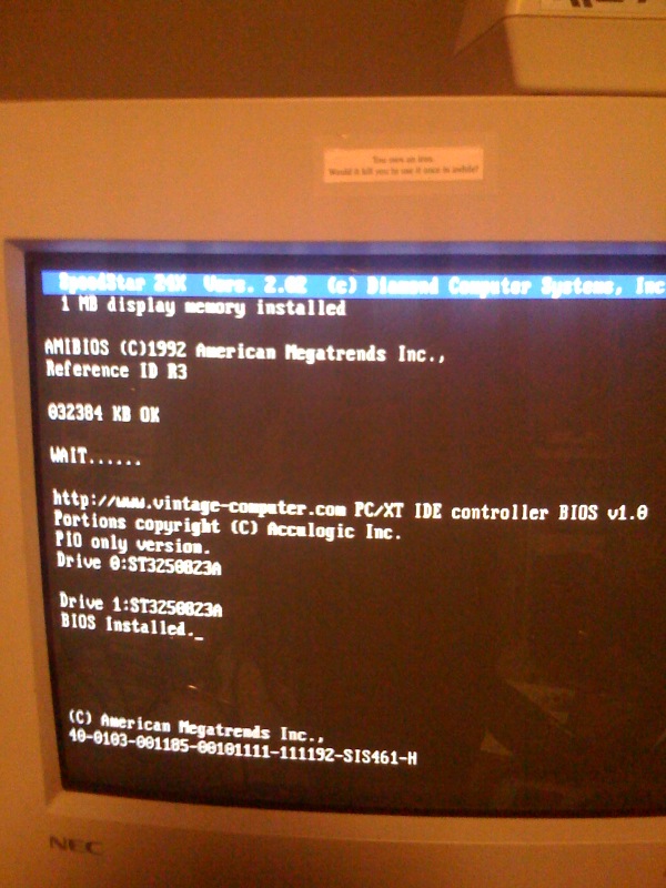
we have an option rom!
I have a bug-I don't actually have 2 drives. oh well.
 
I'm happy to provide assembly services, if needed. Will save export/import costs as components can be bought locally ;) have a good few years' experience with PCB manufacturing
 
here's something to think about wrt the option rom:

If you have a 286->486, and it doesn't have BIOS support for at least 8.4g IDE drives built in, and you have a spare, possibly junked SCSI controller or other device with a BIOS that you could replace, you could replace the BIOS chip on an old card with my option rom, and it'll upgrade your onboard BIOS support to give you a big hard drive. The IDE controller in your machine would need to be using standard IO addresses (ports 1f0-1f7), which should be common.

if I could get some folks to do that, that would provide me with a more robust testing grounds, as i'm sure there are folks using some obscure disk utilities out there and alternate operating systems than just DOS 6.22.

Just to be perfectly clear, this is not going to work on an XT or PC-you will need a 16bit IDE controller for this to work.

This could be another option for another PCB too. Just a plain ole plug in card that has nothing but a BIOS on it for upgrading your INT13 support.
 
Not too long ago Promise used to sell an IDE BIOS that did exactly that - it was a small card with a ROM on it that used the existing controller elsewhere in the machine. One would 'disable' the existing controller by setting the drive type to zero in the BIOS, which would still allow the hardware to respond if it was accessed. The Promise ROM would then do the rest.
 
you have a spare, possibly junked SCSI controller or other device with a BIOS that you could replace, you could replace the BIOS chip on an old card with my option rom
if you use your computer networked, how about network boot rom socket ? You won't loose any slot for junk card
 
Not too long ago Promise used to sell an IDE BIOS that did exactly that - it was a small card with a ROM on it that used the existing controller elsewhere in the machine. One would 'disable' the existing controller by setting the drive type to zero in the BIOS, which would still allow the hardware to respond if it was accessed. The Promise ROM would then do the rest.

Yep, the Promise DriveMax. I have a few of those ROMs in my computers. Modified one to always install regardless of BIOS drive settings and skip the secondary IRQ check to speed things up.

This is a cool project hargle. I Don't need really need an 8-bit IDE anymore now that I got a TMC-850 and a SCSI-IDE bridge but I might buy a few just to have around. :cool:
 
ok gang, good progress was made today.

Here's stab #1 at a working option ROM.

Tested:
1. single drive, drive was 10gig.
2. DOS 6.22 fdisk sees the drive as 8033MB
3. partitioned into 4 drives, each ~2gig each (the maximum for FAT-16)
4. formatted C:/s and copied other files to the drive
5. booted to C:
6. formatted d: and copied files to the drive
7. ran chkdsk and scandisk without errors
8. put drive in a via epia board, and was able to boot to it, see all the files. Drive appears to be completely interoperable with my single modern test system

Untested:
1. drives smaller than 8.4gig - i can definitely see a possible issue there.
2. 2 drives
3. any other OS other than 6.22
4. interoperability with other modern platforms with AMI BIOS or other
5. any extended INT13 functions. There will absolutely be bugs there.
6. any funky INT13 commands like format track or diagnostics
7. most disk utilities, benchmarks
8. failing drives with ecc errors or something to test the error reporting

To use this option rom, you will need a card with a blank socket on it, and a 16bit IDE controller elsewhere in the system. As suggested by StickByDos, a NIC card typically has a blank rom socket on it-this could be a brilliant solution!

At the moment, it's a 4k option rom. It will likely not grow beyond this size.

Set your drive types in CMOS setup to *none*! If the onboard BIOS sees the drive there, my bios will not hook INT13 and won't install.


To build this option rom, you will need MASM 6.11 (or higher) in your path, and I use debug.exe to help truncate the file to the correct size. Just type "build" at the DOS prompt to build it. You should have a 4k file called oprom.bin when you're finished.

The code is still fairly nasty looking, but I figured this is a bit of a milestone, so might as well get it out there.

have fun!
 

Attachments

  • oprom.zip
    2.1 KB · Views: 1
  • oprom_src.zip
    54.6 KB · Views: 1
Back
Top