• Please review our updated Terms and Rules here

IBM 5154 Troubleshooting

Do you guys have the real IBM EGA monitor schematics ? I recall
sending the PGA monitor schematics to a couple forum members
awhile back. I think the PS is very similar between these two monitors.
If anyone has the actual EGA schematics I'd like to get a copy.

I put a copy of the PGA schematics at the following link. One of
these shows the CRT connections, but I'm not sure its the same as EGA.

http://home.rr.com/mwcompu

Added the missing Sheet 4 at the above link ..... remember, this is for the PGA monitor
 
Last edited:
Do you guys have the real IBM EGA monitor schematics ? I recall
sending the PGA monitor schematics to a couple forum members
awhile back. I think the PS is very similar between these two monitors.
If anyone has the actual EGA schematics I'd like to get a copy.

I've got them--PM me with your email and I'll get to scanning.

Edit No I don't have them after all--the O&A doesn't include a schematic for that display!

Anyone got one?
 
Last edited:
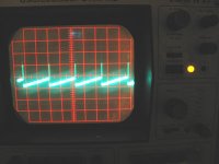
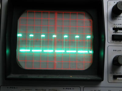
I´ve made a pic from my scope messuring at point "M". Point "O" and "Q" are equiv. I will search for the fault in the heater tomorrow, because I came back from work very late...

Hanno.


By the way page 4 of the schematics are still missing and I cannot download from the new link. Would be great if anybody could send me a copy. I will upload it on my website which is online for 12 years without any advertising or flash problems. Thank you!
 

Attachments

  • 5154os1.jpg
    5154os1.jpg
    20.6 KB · Views: 1
sheet 4

sheet 4

PM me your email or a spot where I can put it. I just got it from someone else earlier.
It looks like you have drive to your guns.
Can you check if you have a TDA 2594 somewhere in your horizontal section, possibly close to the flyback ?
patscc
 
Sorry guys, I put those schematics out there, its some new Roadrunner homepage
interface, therefore the advertising :-(

So I'm not sure if everyone can access them. I don't see anything about setting
access, so I thought it was totally public.

Can anyone access them ?

http://home.rr.com/mwcompu

By the way page 4 of the schematics are still missing and I cannot download from the new link. Would be great if anybody could send me a copy. I will upload it on my website which is online for 12 years without any advertising or flash problems. Thank you!
 
Ega

Ega

I do have an EGA I can pull apart this weekend if the schematic doesn't pan out. The OP is checking to see if a key IC exists, and if it does, we can probably work with it since hopefully any fault won't be in the input area.
patscc
 
Pin 6

Pin 6

See if you get the flyback pulse on pin 6. There's probably a 47kOhm resistor that goes from pin 6 on the TDA to the flyback, try to take the reading between pin 6 and the 47k resistor rather than between the resistor and the flyback.
patscc
 
Going back to Hanno's described fault, I'd be looking to see if you get EHT generated (Woomf & crackles when you power up) if so then the fault is only in the heater circuit, which is just a winding on the transformer, an inductor, and the two receptacles in the crt socket that the heater connects to.

With the amount of smashing that appears to have gone on on your monitor, I'd be looking for dry/fractured joints in that circuit, especially on the EHT transformer (mb102), (this also applies if there's NO EHTl)
Look at the variable inductor that controls the heater current, it's top heavy and liable to wobble a lot, and resolder the tube base.

If there's no EHT, then check pin 3 of the 2593 for the pulse which (ultimately) drives the EHT chopper transistor. if that's there, check for dry joints around the chopper transistor, and the transformer driving it. then check the transistor itself, also check the RB101, it's a half watt resistor, so will have been running hot.

If you can't easily get to the 2593 while it's running (without risking your life) just do the dry joint & transistor checks first.
Personally, I'd just resolder the EHT transformer anyway. Use LEADED solder, as unleaded & leaded tend not to mix well & for some reason you tend to get crystallised joints in high frequency chopper circuits (I don't think it's a myth)

You really have had a "baptism of fire" (hopefully not literally!) with this monitor haven't you!
 
Going back to Hanno's described fault, I'd be looking to see if you get EHT generated (Woomf & crackles when you power up) if so then the fault is only in the heater circuit, which is just a winding on the transformer, an inductor, and the two receptacles in the crt socket that the heater connects to.

You really have had a "baptism of fire" (hopefully not literally!) with this monitor haven't you!

I think the monitor doesn´t want to be repaired or is just too lazy to work again.
A bit early to retire after lets say 20 years of work if you ask me!


The heater circuit isn´t working - that´s for sure! Well I don´t see the differences between red and green, however I don´t care if the tube would have a green glow at its neck, but there´s nothing.

As I´ve mentioned, the display shows nothing at power up, but the monitor makes Wooommmpfff (sound, no smoke, no explosions..) and I can hear the charging (don´t know how to expain that in english...).

The 2593 is placed near the screen and under the tube neck, so I had to remove the plastic housing:


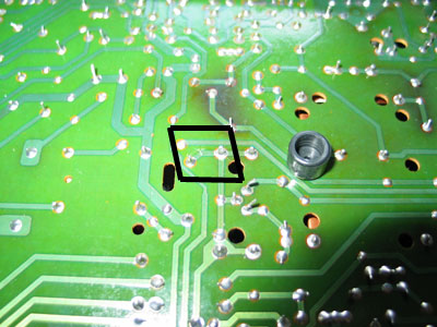
What did I find on the circuit board??? Right, a broken trace!

5154bahn.jpg


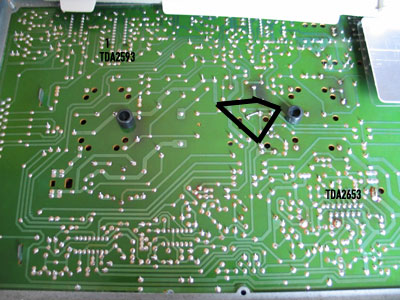
and here´s a pic of the whole board. The repaired trace is marked.

5154haupt.jpg


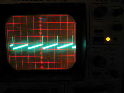
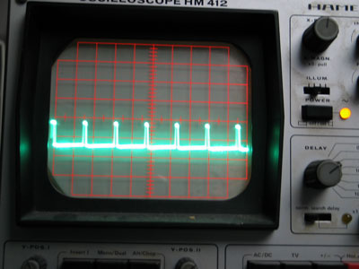
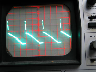
Moreover I have thrown a few photos of my scope.

Here´s the diagram for point M,,O,Q (again)
5154-moq.jpg


Here´s the diagram of the TDA2593 Pin 3
5154-2593P3.jpg


Here´s the diagram of the TDA2593 Pin 6
5154-2593P6.jpg


Here´s the diagram of the TDA2653 Pin 6
5154-2653P6.jpg


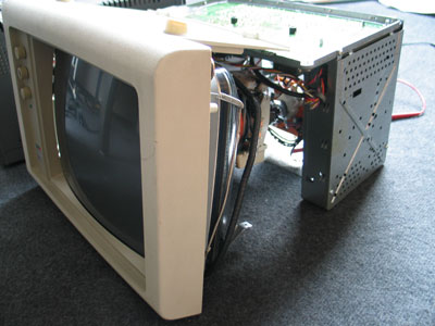
And last but not least a pic of the electronic scrap
5154-zerlegt.jpg


Hanno.
 
Pin 6

Pin 6

Well, the flyback pulse in pin 6 looks a bit odd, but at least you've got one. What, by the way, is the vertical set to on the scope for that reading ?
Since the deflection circuits seem to be going, it looks like you're getting HV, only no image since it sounds like there's no heater going.
Were you able to check the resistance of the tube on the CRT ?
Can you check the resistance of the windings that feed the CRT heater circuit on the flyback ?
Well, I got my 5153 into the house, which is a good start, this week I'll open it up and take a picture of the tube's neck so you can see what the glow should look like, and I'll measure the heater voltage. If it's 6.3 or 12 volts, you're in luck, you can build one your self, derive it of the low-voltage supply, and you're good to go without having to replace the flyback.
If, on the other hand, it's the actual heater that's blown...
patscc
 
Hi patscc,

I also own a working 5153 and I can imagine, how the glowing should look like, however I am not sure about the heating pins of the tube. Am I right, that the heating coil is connected through the tube socket???

I am able to messure a resistance of about 6-8 ohms between Pin 4 & 5 of the tube pins and between 9 and 10. Pin 4 is not connected to the tube socket, so I think the heating should be pins 9 and 10. Pin 9 is connected to ground and Pin 10 of the tube is connected to Pins 4 and 5 of the Connector 1 of the PS.

Unfortunately, the schematics tell me, that the pins 4 and 5 are not used, but that might also be a difference between the PGA and the EGA.

It´s easy to power the circuit with 5V or 12V DC, but until I am not sure what I am doing, I won´t do that. I cannot see anything about the heating in the schematics.

By the way, I cannot messure a voltage between Pin 9 and Pin 10 of the tube. In case this is the heating circuit it is definately broken.

A last question for today: I am wondering that the screen stays dark without the heating. Has somebody checked that so far?

Hanno.
 
dark

dark

The screen is naturally dark.
Without a hot cathode, not enough electrons are emitted to be accelerated by the anode potential, so not enough hit the phosphor to glow. If the vacuum of the tube is slightly compromised, you can get an ion stream to transport the electrons, which looks kinda cool, but unfortunately means the tube is effectively dead, but I don't want to get side-tracked.

I'll post back as soon as I look in my 5153 so we all know where the heater pins are and where a handy spot for measuring them is.

The 6~8 sounds about right, though, I think.
patscc
 
Schematics indicate a heater between 4 or 9 and 5 or 10 so that looks right, you're probably (probably!) on the home straight.

It's a high frequency AC voltage driving the heaters, you measure 6-8ohms across the heaters, so that's ok, now measure to see if there's a circuit through the inductor, or more usefully, through the inductor, heaters, tube base, and right to the heater circuit connections of the tube base board, so you can eliminate that part of the circuit.

Next (as you've exposed the main pcb anyway) RESOLDER!!!!!
There are probably loads of crystallised joints on the main board, suck (a bit) & redo all the joints on the transformers (both of them) the power transistors, and anything else that looks as if it's connected to a hot component, or looks a little grey & tired. The heater voltage is only low so it'll get stopped by the tiniest of cracks, other cracks will shop up in time, in annoying ways, if you do it now, it will save a lot of stripping down later.

I would bet on the problem being a cracked joint on one of the legs of the EHT transformer, also check for a broken pcb track right next to the pad, it's another stress point.
 
The solder points all look quite shiny. However I´ve done some resoldering and thanks to "nige the hippy" I´ve found another broken trace when I was resoldering a 1/2W resistor next to the transformer. The pad had connection to the resistor but not to the trace. Once repaired, I´ve resoldered all 1/2W resistors, the transformer of course, the TO-3 style transistors and some other points which seems to carry a higher current.

One hour later I finished the work and was able to power the 5154 again. What happened? Nothing, the heating is still ooo. :)

OK, I will do some messuring on the circuit board that is plugged on the tube. The tube socket seems to be okay, although pin 12 of the tube has no connection to the board. Pin 12 of the socket is soldered to ground, but has no inner socket contact.

Hanno.
 
Back to the heater. I´ve veryfied, that the heater pins are indeed 9 & 10. And these are connected to the PS. With a 5VDC transformer on the PS connector the heater is glowing. From my point of view, this should be a high frequency 6,3V Voltage and 5VDC might destroy the kathode.

I´ve disassembled the PS again and couldn´t messure any voltage in the matching transformer pins. Since I had to replace the cond. (it was shorted) which was switched between 6,3V AC and GND I assume, the transformer might be the problem. Yes I know, transformers are the least component, which will be destroyed, however there isn´t any other circuit.

Hanno.

What I will do next: I am going to buy a 240V-->5VAC transformer and will power the heater from the new circuit. I know this isn´t a high frequency source but hopefully this will work.
 
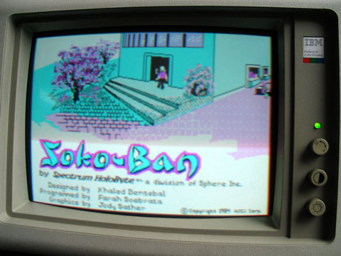
With a 5VDC heater voltage I connected the 5154 to my IBM CGA card (EGA is comming soon).

After half an hour of adjustments I was able to play sokoban. OK, the picture isn´t that sharp, but that has to do with a too low heater voltage.

The new 6VAC supply will be connected to the original PSU circuit (I will solder it to the disconnected transformer pins.)

I would like to thank everybody who helped me to fix my moni.

Would be great if somebody could messure the heater voltage on a working 5154. Best to do that is at connector 1 of the PS, between pins 2/3 - 4/5.

Hanno

5154-sok.jpg
 
Nicole,

Once I asked a woman in the Grafenvoer Post Exchange where she was from. "Aachen", she replied - and it sounded so beautiful.

Can't you ask somebody who worked on monitors how to go about fixing yours, instead of trying something that you aren't sure of to try to fix it?

Sean
 
Back
Top