• Please review our updated Terms and Rules here

Mac misadventures

If you're poking around the display be careful of the EHT (connection on the side of the CRT). A CRT acts like a capacitor, storing a charge for a surprising amount of time after switch-off. The EHT will be quite a few kV.

Touching it is unlikely to kill you (very low current) but give you a reasonable boot and a hell of a fright!

If you had some kind of display you've probably got EHT. My knowledge of TV circuitry is basic but I suspect you've got line drive as well, so your LOPT is probably ok.

Do you have any contacts in the TV service industry? If so it may be time to call in some favours :)

Also drop me a PM re the manual, there's a chance I may be able to help.
 
Partially thanks to info. from a link arjoll sent me, I MIGHT have cracked this problem.

I'll find out when I replace the suspected faulty component tonight.

Tez
 
Back to the drawing board...

Back to the drawing board...

Well, that didn’t work.

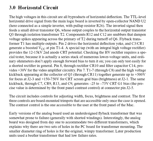
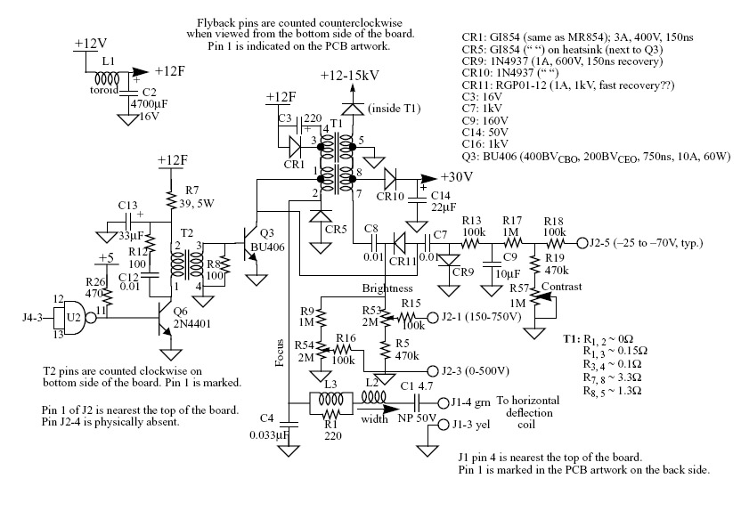
I’ve come to a brick wall with this one. Before I consign the Mac SE back to the parts bin, is someone able to look at this circuit diagram and the associated text at the end of this message and see if there is anything else I should check?

The circuit is for a Mac Plus but (apparently) the SE uses the same horizontal circuit. Furthermore, the codes on the diagram don’t refer to exactly the same components on the SE (The T1 Flyback is called T2 on my analogue board for example) but I’m sure I know what they are referring to.

Here are some facts.

  • The symptoms are a completely back screen. No raster. A faint light does appear in the neck though.
  • I have a working Mac SE/30 which I’ve used as a standard to make comparisons. It has the same type of analogue board.

I suspected either the flyback transformer (T1), C3, CR1 or Q3.

  • Voltages on T1 pins 1-4 on the Mac SE are found 12v
  • Voltages on T1 pins 1-4 on the working SE/30 are 20v!
  • Voltages on T1 pins 5-8 on the Mac SE are practically zero. No high voltages (hence a back screen)
  • Voltages on T1 pins 5-8 on the working SE/30 are as indicated on the diagram (i.e. very high!)
In the description of the circuit it says ..”and C3/CR1 generated a boosted Vcc at pin T1 1-4”. I read that to mean that 12v is boosted to about 20v. Certainly on the working SE/30 there is 12v one side of the C3/CR1 and 20v to other. Given that in the broken SE there is NO boosted voltage, I figured maybe C3 was faulty and replaced it. No change. I then replaced the diode CR1 even though is seemed ok. Still no change!

I’m stuck.

I measured the resistance across the Q3 transistor and it’s similar to the working one. It doesn’t appear damaged. I’m not sure if this transistor would cause the problem anyway, would it?.

If it is not C3/CR1. why then is the voltage on the T1 input pins 1-4 12v and not 20v? What SHOULD boost this voltage up? I figure this lower voltage on pins 1-4 is why the flyback transformer is not firing high voltages out of the circuitry connected to 7 and 8?

Is the flyback itself the likely culprit? Would this be causing the low voltages on those pins (even though they seem to be input pins)?

Any comments most welcome. If it is the flyback transformer I’ll just keep the SE for parts. They are hard to get and expensive to replace. However, I just want to check if there is not some obvious easy-to-replace component that I’ve missed?

Thanks in advance.

The full PDF the digrams below are sourced from is at
http://home.earthlink.net/~gamba2/images/plus_analog.PDF

Tez

2009-04-09-mac-horz-circuit-text.jpg


2009-04-09-mac-horz-circuit.jpg
 
I'd really be looking at Q3 (out of circuit) by now with a diode-test setting on my meter, sometimes they go short collector-emitter, sometimes short emitter-base, sometimes they just pop, and sometimes the legs fracture with differential expansion between the transistor & the heatsink, all of which will kill the EHT & 12V. measuring in-circuit won't give very conclusive results, as the transformer windings are low resistance.
I'm not sure if the BU406 has an internal diode pointing upwards between emitter & collector, so don't be surprised if you get a 0.6V reading with emitter positive to collector negative.
 
Are the voltages at T2 the same on both machines?

I had a go at this before posting. Believe it or not it's quite hard to know. Main problem is knowing exactly WHERE the pins come out on the back of the circuit board. I can see where the transformer is positioned but at the other side of the board it's hard to know what pins are its pins and what pins belong to other components lol. Things are crammed up in there.

Anyway, I'll try again. Thanks

Tez
 
Last edited:
I'd really be looking at Q3 (out of circuit) by now with a diode-test setting on my meter, sometimes they go short collector-emitter, sometimes short emitter-base, sometimes they just pop, and sometimes the legs fracture with differential expansion between the transistor & the heatsink, all of which will kill the EHT & 12V. measuring in-circuit won't give very conclusive results, as the transformer windings are low resistance.
I'm not sure if the BU406 has an internal diode pointing upwards between emitter & collector, so don't be surprised if you get a 0.6V reading with emitter positive to collector negative.

Hi Nige,

Yes, this one I checked out before posting too.

When you say out of circuit, do you mean with the power switched off, or desoldered?

I don't have a specific diode tested on my multimeter. However, I believe you can do this just using a continuity setting, yes? It seems to check out ok (I get readings similar to what I'd get on a diode between base and emmiter and base and collector i.e. no continuity one way and a small amount of resistance the other way) and whatsmore the reading are quite similar to the one on the working SE/30.

However, I'll check again just to make sure.

Tez
 
Yep, out of circuit as in removed from the board. Otherwise the resistance through the components round about Q8 may throw your readings off.

If that doesn't reveal anything: Have you compared the signals on the other side of T2? Base and collector of Q6 would be good test points. If the pins are hard to reach, you might be able to latch onto other parts connected to them.
 

Yep, thats the doc I started with. It points to the general area most likely at fault but as all components looked OK and tested ok as far as I could measure them, I wanted to islolate the exact one using a circuit diagram and testing equipment before I started to remove and replace things. I thought I'd found the culprit (the 220 capacitor on Pin 4 of the flyback) but...apparently not.

Incidently, for those that may be reading, the component identifiers in the web document posted by unknown_k are different than those in the circuit diagram I've pasted above. The diagram is for a Mac Plus (couldn't find one for the SE). The SE and SE/30 have the same horizontal sweep circuit but the components do not have the same identifiers.

Tez
 
The faint light is good, it means you've got CRT heaters.

I presume you have some signs of life around Q6? And if you turn the brightness up you get no blank raster?

I'd suspect Q3 as a possibility as well. They're around NZ$4 from Farnell so not an expensive part to try. Replacing all the electrolytic caps isn't silly and will only cost a couple of dollars.

Before that it might be worth testing the LOPT (flyback transformer). You'll need to discharge the filter caps and the tube (which acts like a big cap) through a high value resistor, then check here for some basic tests.

I can run that circuit past a friend who is a electronics tech and has sorted out a Sord monitor (with no circuit!) for me, but with it being Easter it will be next week before I have an answer.
 
I presume you have some signs of life around Q6? And if you turn the brightness up you get no blank raster?

Yes to both. Life around Q6 and there is no raster at all.

OK, some measurements. Codes refer to the circuit diagram, NOT the codes in the SE/30 repair web document (which are different)

  • Q3 emitter - 11v (Non-working SE), 20v (working SE)
  • Q3 Base/T2 pin 3 - 0.1v (Non-working SE), 0.7v (working SE)
  • T2 pin 2- 11.4v (Non-working SE), 8.9v (working SE)
(T2 pin 1 and emitter of Q6 very similar to the T2 pin 1 readings as you would expect)

  • Q6 base - 0.46v (Non-working SE), 0.39v (working SE)
The 20v and 11v on the T1 pins 1 to 4 seems a significant difference. Is it likely to be though? If so, would it be the solely the result of the Q3 transistor or is the voltage on that side of the transistor affected by other inputs to T1? As I understand it Q3 is a power transistor whose function is to pulse voltages on and off phase to get a horizonal sweep. Is this correct? If so, could I use a scope to test it?

I can run that circuit past a friend who is a electronics tech and has sorted out a Sord monitor (with no circuit!) for me, but with it being Easter it will be next week before I have an answer.

Thanks Andrew, but it's not worth bothering anyone about (except for the guys on here of course...we like that kind of thing :) ). This is really just a spare (I have another 3 baby macs already!). It's more of a challenge and a learning exercise more than anything else. I want to figure out exactly what it is and, if it is a cheap component, replace it. If it is not a cheap or easy to get component (i.e. the flyback) I'm not going to worry about it.

I do want to diagnose it though.

So, based on those voltages does Q3 still look likely? I'm sure extracting it won't be easy and I suspect it will be a destructive test (in that I might have to cut it out). Would a scope tell me anything?

Andrew, will Farnell ship single components like that and don't they have to import them (shipping charges?) I have a feeling the minimum order is $10.

Tez
 
Fault found?

Fault found?

Ok, I removed the Q3 transistor very carefully so I could replace it if needed.

A transistor can be thought of as two diodes, between the base and collector and base and emitter, right?

A check on the base<--> emitter showed ok. About 500 ohms or so one way and infinite resistance when I swapped the probes.

A check on the base<---> collector showed infinite resistance BOTH ways! This is unusual, even for one of these power transistor right? I should have got a reading similar to the base/emitter check with the negative probe on the base and the positive probe on the collector, correct?

If it's yes to the above, then the problem is indeed Q3. All the evidence does point to it.

Although I'd tested it already, what I've learned is that you need to remove from circuit to properly test these things. If I'd thought about it properly, of COURSE I needed to. Otherwise the current from the base would have simply found it's way to the collector (earth) through the coil at T2, as was mentioned above (Duh!).

Well, you learn from your mistakes.

Anyway, time to see how expensive and available these TV transistors are here in NZ. Certainly my local electronics hobby store doesnt stock it.

Thanks to all who helped with this.

[EDIT]: Looks like I can get the transistor from a local South Island firm here for about $5 total (incl. shipping)

Tez
 
Last edited:
As I understand it Q3 is a power transistor whose function is to pulse voltages on and off phase to get a horizonal sweep. Is this correct? If so, could I use a scope to test it?
You probably need to scope out what's happening before that. If you're just looking at DC voltages then you're not seeing anywhere near the full story, and if you're just looking at AC voltages on a DMM then the readings could get messed up, depending on the waveform - certainly in this case you're not going to see anything useful.

Thanks Andrew, but it's not worth bothering anyone about (except for the guys on here of course...we like that kind of thing :) ).
Yes, but you don't want it to beat you, right :)

Andrew, will Farnell ship single components like that and don't they have to import them (shipping charges?) I have a feeling the minimum order is $10.
They probably do have a minimum, but usually I'll end up spending more than $10 whenever I buy stuff, never hurts to have some stock :) Freight is probably more of a drama, I know RS charge NZ$10 and suspect Farnell are similar. Trade-Tech probably have the transistor as well, didn't think to check there.

BTW Its never a struggle for me to make the $25 minimum Trade Card order level at Jaycar either ;)

A check on the base<---> collector showed infinite resistance BOTH ways! This is unusual, even for one of these power transistor right?
Yes, sounds like a potential problem.

What caused it to fail though? It may just have given up, but that's why I'd look at replacing a few caps, running some basic tests on the LOPT and maybe checking resistors around this area (although they are probably fine, never hurts to check). Out of circuit of course!

Although I'd tested it already, what I've learned is that you need to remove from circuit to properly test these things.
Absolutely! There's very little you can get a good idea of in-circuit.

[EDIT]: Looks like I can get the transistor from a local South Island firm here for about $5 total (incl. shipping)
Grab a couple, just in case :) Never hurts to have a few spares!
 
is the fly back the same for the mac classic? i have a junker here (no sound scsi problems) you can have the analog board for if its the same.
 
is the fly back the same for the mac classic? i have a junker here (no sound scsi problems) you can have the analog board for if its the same.

I'm not sure they are the same. The Classic analogue board is different, I'm fairly sure of that.

Besides, I think I've got the problem identified now. When the transistor replacement arrives, hopefully I'll have a happy Mac SE.

Thanks anyway, I appreciate the offer.

Tez
 
Requiem for this Mac SE

Requiem for this Mac SE

Ok, just to close this thread off...

The new transistor arrived yesterday. First thing I did was to measure the resistance across the various pins. Hmm...strange, quite similar to the one I removed. Maybe that one wasn’t broken after all?

Anyway, soldered it in, assembled, and plugged it in. Still nothing on the screen. Measured the voltages around the transistor on the board. Same as the measurements with the old transistor. Hmm..

Suddenly the hum of the fan changes tone. It starts to slow down. Uh oh...now we have magic smoke...coming from where though? Hard to see...maybe the power supply. Or perhaps further up the analogue board. Fan grinds to a near halt. I switch off.

Ok, so that didn’t go so well (-:

Checking the unit I discover a few things.

I’d forgotten to plug the flyback lead, back onto the side of the screen (duh!). There are just too many damn connectors on an SE..lol

The transistor had a crack in it? This was either from it burning out (maybe this is where the smoke came from), or from me over-tightening the screw which secures it to the Flyback cage.

So, time to take stock. The transistor has cracked and the power supply has failed. The former could have been because I over tightened it. Then again, perhaps it was because I didn’t plug the flyback into the screen? Maybe this is also why the power supply has failed. A cap could have blown in the latter?

It could be that the transistor wasn’t even faulty in the first place and that some undiagnosed issue still lurks (the fly transformer?) along with a few other problems now.

Anyway, I’ve decided to end my Mac misadventure with this machine. I have four other classic Macs (including an SE/30) so there is just not enough motivation to persist with this one, despite the fact I don’t like being beaten by it.

It’s good to write about successes, but more of the learning actually comes from the failures. I’ve learnt to...

  • Always check all leads carefully to make sure they are plugged in. It’s easy to miss one where there are a few
  • Large transistors with a screw hole at the top shouldn’t be screwed in too tightly (although this might not have been the cause of failure in this case)
  • Check components when out of circuit or readings can mislead you
As to the SE, the tube is a useful spare part, as it’s swappable with the other Macs. Cases can be used for aquariums of course (but I'm not really into fish). The SE logic board would make a good wall hanging! Now this is a distinct possibility. :)

Thanks for all the comments and help. They are appreciated.

Tez
 
well, after reading your blog bost on the dead mac se and how you said that you ran out of things to fix, here's my advice for curing that problem:

take work slower! :rolleyes:

well, i guess there's nothing wrong with doing fast work as long as you know what you're doing :D
 
well, after reading your blog bost on the dead mac se and how you said that you ran out of things to fix, here's my advice for curing that problem:

take work slower! :rolleyes:

well, i guess there's nothing wrong with doing fast work as long as you know what you're doing :D

Yes, it's the "know what you're doing" bit where I often come unstuck.

The blog entry linuxlove speaks of is here. Essentially it's a summary of the latter part of this thread.

I am curious about the power transistor though (see blog). Is the middle leg always regarded as the base and should should resistance between emitter and collector always be infinite when measured across the these pins when out of circuit? That's what I've always assumed but maybe these assumptions are incorrect?

Tez
 
Back
Top