• Please review our updated Terms and Rules here

XT reset switch hack

sombunall

Experienced Member
Joined
Feb 18, 2010
Messages
154
Location
Montreal, Canada
I managed to make a really sweet hack for an XT reset switch for my original IBM XT mobo. Do do this hack you need:

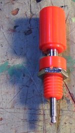
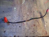
banana terminal with 2mm screw
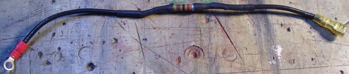
ground wire with round type lug on one end and normal lug on other end
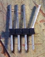
header pin bus (I think it's called that)
soldering iron / shrink wire
100 to 150? ohm resistor

On an XT/AT power supply connector to the motherboard you have power_good which usually is pin 1 and white. According the Repairing and upgrading PCs 5th edition you can do a crude reset of the PC by grounding this pin using 1k to 2.5k resistor. Connecting directly to ground could blow the transistor. I tried and could not reset the computer with anything higher than about ~150 ohms (I only tested up to 110 ohms!). So I chose a 110 ohm resistor I had (it's an oddball value). Why crude reset? If you unplug the keyboard and plug in another the reset will not reset all chips like in an AT so you will need to turn the computer off. This reset will work as long as the other chips with reset pins do not get borked.

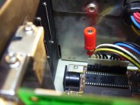
You can screw the banana terminal into the back end of where the power_good wire comes out.

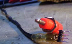
As for the header pins you will need to cut off 4 pins (hacksaw actually) from a line of them that you buy from Digikey for example. Then you will need to bend one of the pins on the end (the long end) in order to make sure it does not contact the one beside it when you insert it into the hole of the banana connector.

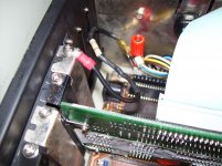
So once you solder in and shrink wire the resistor in series on the wire you just screw the round type lug to one of the expansion card screws that secure it to the case.

If anything is missing with this guide please tell me.

This guide was typed up on my XT with monochrome amber monitor on a paradise EGA card set to 43 rows text inside a telix terminal connected by null modem to a debian linux server. It was typed up on nano. The file was then imported into ultraedit32, converted from unix to DOS to change 0A to 0D 0A, trailing spaces were removed and then CR/LF was converted to a soft wrap. Hopefully I remembered to spell check. Thank you.

attachment.php
 

Attachments

  • terminal_in_powe&#1.jpg
    terminal_in_powe&#1.jpg
    87.3 KB · Views: 2
  • banana_terminal..jpg
    banana_terminal..jpg
    96.9 KB · Views: 2
  • reset_installed..jpg
    reset_installed..jpg
    91.6 KB · Views: 2
  • reset_closup..jpg
    reset_closup..jpg
    91 KB · Views: 2
  • header_pin_bus..jpg
    header_pin_bus..jpg
    35.5 KB · Views: 2
Last edited:
More pics...
WARNING! RESISTOR IN PIC MAY BE TOO HIGH VALUE AND WON'T WORK! I HAD TO REPLACE IT WITH 110 OHMS.

attachment.php


attachment.php


attachment.php
 

Attachments

  • ground_wire..jpg
    ground_wire..jpg
    106.3 KB · Views: 1
  • xt_reset_assembl&#10.jpg
    xt_reset_assembl&#10.jpg
    97 KB · Views: 1
Last edited:
You can get around the limitation by inserting a resistor (470 ohms is fine) between the lead coming from the power supply and pin 1 on the connector. Then you can ground pin 1 with impunity. If you use a pushbutton switch, I'd probaby put a 0.1 mfd capacitor across the switch contacts to smooth any bounce.
 
I would just use an automotive wiring-style inline tap with the wire coming from the power supply, to eliminate the need for the banana plug and header.

michaelg-albums-behind-grill-light-installation-picture43845-heres-tap-i-used-turn-relay-when-highbeams-activated-high-beams-black-green-wire-way-brown-green-wire-low-beams.jpg
 
I reset my XT and 5150 the same way with a small RadioShack push button on the front left just behind the front bezel. I didn't use a current limiting resistor or any debouncing, I just put a tap on the power good wire and simply grounded it out with the button. Never a problem for 15 or so years.
 
I reset my XT and 5150 the same way with a small RadioShack push button on the front left just behind the front bezel. I didn't use a current limiting resistor or any debouncing, I just put a tap on the power good wire and simply grounded it out with the button. Never a problem for 15 or so years.

I agree completely, but if "Repairing and upgrading PCs 5th edition" says that it' will damage things, who are we to disagree? :stupid:
 
I agree completely, but if "Repairing and upgrading PCs 5th edition" says that it' will damage things, who are we to disagree? :stupid:
If you want to be quick and dirty, you wouldn't even need a piece of wire... just solder one end of the resistor to the power supply wire, and the other end to a switch mounted on the back of the case (above the keyboard port). Ground the other terminal of the switch to the case, and you're done.
 
If you want to be quick and dirty, you wouldn't even need a piece of wire... just solder one end of the resistor to the power supply wire, and the other end to a switch mounted on the back of the case (above the keyboard port). Ground the other terminal of the switch to the case, and you're done.

Or, just jam one end of a test probe into the top of pin 1 of the molex connector and slip it out through any convenient hole in the case. Touch the other end to any bare metal on the chassis to reset.

How's that for dirty? :)
 
...and now a reading from the Holy Bible:

From Upgrading and Repairing PCs 5th edition, chapter 8 page 322:

A simple button and wire are sufficient for adding a reset switch, but as a safety precaution, you can place a 1/4 watt resistor with a value between 1k and 2.7k ohms inline with the wire and power_good line to the switch. The reason for adding the resistor is that the power_good signal is provided by a PNP transistor inside the power supply, with its emitter connected to the +5 volt signal. Without the resistor, shorting the power_good signal to ground for a long period can burn out the transistor.

Except I needed 110 ohms, 270 was even too much for my supply as was 1k.
 
cool little hardware hack. i believe Mad-Mike (i think it was him at least) from this forum did the same thing with one of his 8088 systems.
 
I get the impression this (my idea) would be a bad idea, but can anyone tell me why?

My idea would be to use a normally closed button in series with the power switch which when pressed would completely interrupt all power. Perhaps for the sake of saving the monitor, if attached, the pass-through power plug could come before this switch so it wouldn't lose power.

You want to create a pushbutton that is active low to save your monitor from thermal shock because it's plugged into the power supply? Why don't you just plug a computer AC power cable into the monitor? Sounds like you're making trouble where there isn't any. It would be harder to do that than to do my hack and would cause a power cycle anyways and hence thermal shock. :confused:
 
You want to create a pushbutton that is active low to save your monitor from thermal shock because it's plugged into the power supply? Why don't you just plug a computer AC power cable into the monitor? Sounds like you're making trouble where there isn't any. It would be harder to do that than to do my hack and would cause a power cycle anyways and hence thermal shock. :confused:

Active low? What?

I mean a switch...button/whatever...in series with the main power switch, but normally closed (such that you don't need to hold it to keep the power on) which when pressed would have the same effect as flipping the main switch off then back on again.

About trouble where there isn't any, from what I'm seeing, there is a risk using the method described in this thread...so there's always a risk. It's just a matter of what the lowest risk method is. I'm wondering what damage can come from what I've described, not if it's a good idea (generally anything out of original spec will be a not good dea).

The stuff about the monitor pass-through plug is for the people who feel the need to plug their monitor in that way.
 
I mean a switch...button/whatever...in series with the main power switch, but normally closed (such that you don't need to hold it to keep the power on) which when pressed would have the same effect as flipping the main switch off then back on again.
I see a couple of disadvantages compared to a reset switch:

1. It's never good to play about with mains voltage. Something to be avoided if possible.

2. When powering off/on one of these old computers (and even computers today), one generally leaves at least a few seconds between the off and the on. You'd have to do the same with your power switch (for a proper off/on, press the switch for at least a few seconds). Just a disadvantage compared to a reset switch.
 
Active low? What?

I mean a switch...button/whatever...in series with the main power switch, but normally closed (such that you don't need to hold it to keep the power on) which when pressed would have the same effect as flipping the main switch off then back on again.

About trouble where there isn't any, from what I'm seeing, there is a risk using the method described in this thread...so there's always a risk. It's just a matter of what the lowest risk method is. I'm wondering what damage can come from what I've described, not if it's a good idea (generally anything out of original spec will be a not good dea).

What I meant by active low is that when the pushbutton is pushed the power is disconnected as you described. Actually this is not what active low means exactly, sorry. Active low would mean it supplies ground when it is pushed. What I really meant to say was a "push-off" pushbutton.

As for risk, your method is riskier since you actually interrupt the power and create thermal shock. Furthermore you would have to hold it down to drain the capacitors in the supply which would shock them for no reason too. On top of that you would need a much higher rated pushbutton than the one on the case. Your idea is bad. I don't think my idea with my 100 ohm resistor is going to cause any more risk than a real AT reset circuit.
 
I think of three levels of "reset".
  • What you get when you do a three-fingered salute
  • What you get when you drop the Reset line (or ground the Power Good line).
  • What you get when you cycle the power.
There's another level that involves wiping all of the non-volatile storage, but I generally don't think of that as a reset. The first will often get you out of trouble if the system still can recognize and act on keyboard interrupts. The second, if it can't. The third resets all of the peripheral devices (e.g. disk and tape drives) that do not respond to the PC's reset line.

The last, I prefer to cycle the power using a switch, rather than a normally-closed momentary contact pushbutton in the power lead. The reason is that I want to give things a chance to settle and the pushbutton has the hazard of removing and reapplying power too quickly (as sometimes evidenced when you encounter brief power outages).
 
not to mention that if your computer gets into a state where it's hung, you can't park your hard drive heads before dropping power on the whole system. With just a reset hack resetting only the motherboard/cpu, then you can get back to a point where you can safely shut down your machine. It's funny that older machines didn't have reset switches when those are the ones which often need to be reset back to do a safe shutdown more than newer machines with self-parking (IDE drives)
 
Heh, thanks folks. That's what I was looking for.

I had a feeling it could cause problems doing it that way, but wasn't sure. As my PS/2 30-286 doesn't have a reset button I've been looking at ways to potentially implement something so it's best to ask questions rather than blow things up.
 
Back
Top