• Please review our updated Terms and Rules here

PET Alive! - Pet Hospital

Relax...

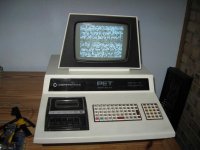
It kinda looks like your PET's going around in circles, i.e. a loop in the E space; any chance you could replace that UD7 ROM with the one from the other board (that's the one that's socketed, right?)

You just might be lucky after all.

I've just done exactly that Mike,......swapped the rom and checked p20 . but no difference? if this pin is chip select, I can't understand why the line is pulsing? ......Harry ( can I have AC on this line ?)
 
I've just done exactly that Mike,......swapped the rom and checked p20 . but no difference? if this pin is chip select, I can't understand why the line is pulsing? ......Harry ( can I have AC on this line ?)

did a quick check on the 6545 ( crt controller) p25 c/s, stays high, Hence no screen responce , For some reason I thought this was going to be easy!! something is blocking,
 
did a quick check on the 6545 ( crt controller) p25 c/s, stays high, Hence no screen responce , For some reason I thought this was going to be easy!! something is blocking,
Well, if it doesn't tweedle and really never selects any ROM other than UD7 then it's probably never getting as far as talking to the 6545 anyway. CS lines will pulse low every time the IC in question is accessed, so normally almost every chip should be periodically selected (i.e. the CS line would be 'pulsing').

If UD7 is really the only chip ever selected then it would seem to indicate that the CPU is looping through some instructions in the 'E' ROM; since the ROM is apparently OK, then there is presumably a problem with the data being read or the address that's supposed to be read.

Any other ideas?

Time to put the 'scope probe on those address and data lines.
 
What you folks are doing is really great! I commend you. As a regular listener of Earl's retrobits podcast I was inspired to bring my Pet to the hospital. I got my computer from a person (friend of a friend kind of thing) who said it was working, and I have no reason to not believe him. But somehow during shipment something must have happened. I've had the system about a year now and there has been no change in the patient. I have tried pulling and reseating all chips with no luck (you gotta realize I'm a software guy, not a hardware guy, but I'm not afraid to try things out. But with this system I want to go very slowly). Attached is a picture of my system. Isn't it nice? I like it.

Also attached is the screen. I don't like that.

Any ideas on what is wrong?

Thanks!

Paul
 

Attachments

  • IMG_2486.jpg
    IMG_2486.jpg
    92.3 KB · Views: 1
  • IMG_2484.jpg
    IMG_2484.jpg
    91.9 KB · Views: 1
Hi Paul, and welcome to Admitting.

Very nice indeed; congratulations! One of the much desired early models.

More often than not, that problem is caused by a bad ROM chip or socket. It wouldn't hurt to carefully check the ROMs just in case you inadvertently bent a pin underneath when you removed and replaced them; you could also try pushing on each end to slide them back and forth in their sockets.

Unfortunately, the downside of the desirable early models was that they most commonly used non-standard RAM and ROM chips for which there are no current direct equivalents, and which adds a little extra difficulty to diagnosing and repair.

So, what are the numbers on the RAM and ROM chips?

And where on (or off) this planet are you located?
 
H MikeS. Or should I say Hi Doc!

It has 6540 and 6550 chips. I know what you mean about the pins. I used a good chip puller (with a ground strap on my wrist) when I pulled them out. That was the easy part. But putting them in! That was the scary part. But no pins were (are) bent. I will try pushing on the ends a bit as you suggest.

I'm located in Colorado, near Denver.

Paul
By any chance, do you have access to an EPROM programmer and some 2732s or larger?
 
But putting them in! That was the scary part. But no pins were (are) bent.

Paul,
As you may be pulling and inserting a lot of the 28 or 40 pin DIP devices, you might consider going to the local Radio Shack and investing in a 40 pin insertion tool similar to the one shown. This will keep the pins from bending.

It looks from your screen that you are not getting far enough into the boot process to setup the screen. Do you have a character blinking somewhere in the upper left quadrant where the cursor should be? Does the screen react to any key input? If not you may have a bad ROM as Mike suggested.
-Dave
40pin.jpg
 
By any chance, do you have access to an EPROM programmer and some 2732s or larger?
Sadly no. What are you thinking? I always wanted to get an EPROM programmer and start learning about it. Maybe now is a good time?

As you may be pulling and inserting a lot of the 28 or 40 pin DIP devices, you might consider going to the local Radio Shack and investing in a 40 pin insertion tool similar to the one shown.
Will do!

Do you have a character blinking somewhere in the upper left quadrant where the cursor should be? Does the screen react to any key input? If not you may have a bad ROM as Mike suggested.
No blinking characters, no screen reaction to keyboard input.

Paul
 
the best to analyze that problem if you use the PET RAM/ROM expansion
http://freenet-homepage.de/x1541/hardware/petram.html
you put that into the processor socket; you can set via DIP switches if only the memory or also the ROM or both together are substituted...
I use it on my defective PETs.. Nicolas Welte sells them for around EUR 30-40 which is around $40-50...
A substitution of just the ROM's for the 6540 ROMs has been built by an Austrian here.. he sells it for around EUR 15 ($20).. it works fine, I helped him testing
 
you put that into the processor socket; you can set via DIP switches if only the memory or also the ROM or both together are substituted...

This would be a handy solution especially for the old style 2001 PETs with the hard to substitute ROMs and RAMs.

Do the ROMs on the system board have to be removed for this to work? From looking at the switch settings for configuration, it seems you must replace all the ROMs at once rather than one at a time for troubleshooting. Too bad as that would have been a wonderful diagnostic tool if someone intended to replace only the one bad ROM to keep the PET as original as possible.

I hope, if you buy a complete unit from Nicolas, it will come pre-programmed? It might be a pain to transfer files to the PET from a PC and run flash software if you do not have all the transfer cables and software.
 
Edit: As usual, Dave snuck in there with the same idea while I was typing...

Sadly no. What are you thinking? I always wanted to get an EPROM programmer and start learning about it. Maybe now is a good time?
...
Paul
I'm thinking the same as Alker's second suggestion: not to take away from his version but one of our list members (Jim Brain) also makes an adapter (as well as various other neat Commodore goodies) that lets you put a standard EPROM into a 6540 socket. With that and a programmed EPROM you can replace each of the ROMs one at a time to find the bad one (if that is indeed the problem) and replace it, or if you're concerned about authenticity, you'll know which original one to try to find.

There are other ways to test the ROMs but unless you find someone with a matching PET and send him your ROMs to test (or persuade him to lend you a good set) that's probably the easiest way.

Alker's first suggestion is a little more expensive and not 'authentic' (but easily reversible), but it replaces all the non-standard ROM and RAM chips with one small plug-in board.

Just for info, what are the ROM part numbers? (9014xx-xx)
 
Last edited:
did a quick check on the 6545 ( crt controller) p25 c/s, stays high, Hence no screen responce , For some reason I thought this was going to be easy!! something is blocking,
Haven't forgotten you, Harry; had a chance to look at those signals with the 'scope yet?
 
Well, if it doesn't tweedle and really never selects any ROM other than UD7 then it's probably never getting as far as talking to the 6545 anyway. CS lines will pulse low every time the IC in question is accessed, so normally almost every chip should be periodically selected (i.e. the CS line would be 'pulsing').

If UD7 is really the only chip ever selected then it would seem to indicate that the CPU is looping through some instructions in the 'E' ROM; since the ROM is apparently OK, then there is presumably a problem with the data being read or the address that's supposed to be read.

Any other ideas?

Time to put the 'scope probe on those address and data lines.

Hi Mike, yes I can set up the scope, but I would need some guidance on obtaining the results you need. but before I do that, can you, or someone identify the items in the attachments I have posted, I don't know if they are of any help? I don't know if anything works, and worse, I don't have any info on how to use it! The items were formally used by a Commodore engineer, I have had these items many years , and I never had the need to use any of it until now, and who knows this might be a good time to learn how to use them,
thats if someone has some details about the correct method of use? what do you think? ...... Harry
 

Attachments

  • P1030087a.jpg
    P1030087a.jpg
    37.3 KB · Views: 1
  • P1030086a.jpg
    P1030086a.jpg
    38.2 KB · Views: 1
  • P1030084a.jpg
    P1030084a.jpg
    43.1 KB · Views: 1
  • P1030088a.jpg
    P1030088a.jpg
    48.5 KB · Views: 1
  • P1030085a.jpg
    P1030085a.jpg
    58.6 KB · Views: 1
Haven't forgotten you, Harry; had a chance to look at those signals with the 'scope yet?


ok, I have done some checking with the scope, most address signals appear ok , other than they are locked, not moving or jittering like when working, the abnormal reading is on p15 (A6) and p16 (A7) both shows stuck at about +1.6v not 0v as per the working board, I assume unless these address lines are correct nothing will progress, and data will be of less priority, the signals on rom UD7 seem quite ok but again frozen. nothing progress's , sorry for being so vaque I am on a learning trail with this fault, if you need better or specific pin readings just let me know, i'll try my best! Maybe I can do some scope images if needed?
I quess this shows why whole boards where often replaced,... time was probably more valuable than a replacement board..........many thanks .... Harry ( time for bed )
 
You guys are doing a GREAT job here!

Harry, it looks like your issue is proving particularly thorny. Yes, replacing boards would have been far less costly in the day than trying to diagnosis anything that way beyond swapping out a suspect IC. Trouble is, in the present day it's not so easy to get a replacement! :)

Tez
 
the abnormal reading is on p15 (A6) and p16 (A7) both shows stuck at about +1.6v not 0v as per the working board

This would possibly indicate that the traces from these two lines are shorted together. If one line was supposed to be high and the other low, the result of shorting these address outputs together would be both at ~1.5V. Can you ohm these lines with power off and see if they are shorted together?
 
can you, or someone identify the items in the attachments I have posted,

I wish you had some manuals on this interesting stuff. The diagnostic clips that say 40/80 column 50Hz seems to be a tester for the CRT monitor.

What is inside the 8000 series tool kit?
-Dave
 
I wish you had some manuals on this interesting stuff. The diagnostic clips that say 40/80 column 50Hz seems to be a tester for the CRT monitor.

What is inside the 8000 series tool kit?
-Dave
It sure does look interesting...

Maybe Anders knows something about it? 50 Hz suggests that it might have been for the European market.

I'll post a link on CBM hackers; maybe someone there knows something.

@harry: When you say most address lines are OK, do you actually mean that they are a steady 0 or +5V? And are you sure that a6 and a7 are 0V on the working board?

How's the 6502 clock signal?

But Dave is right; 1.6V isn't good, and usually means a high/low contention.
 
Back
Top