• Please review our updated Terms and Rules here

Commodore PET 4032 Problem

I would check pinout and some more documents/discussions before swapping chips.

Emptymind early on posted a picture of the motherboard. It looks identical to the 3032 boards I have, with four large chips: 6502, 6520, 6520, 6522 so you're probably right it has no 6545 chip, my fault. On the other hand it means I could test-drive some of my last spare boards, in order to diagnose which are still good to go. If no progress is made on his board then there would exist an alternative branch.

Thanks Anders.

Quick Update:

When I opened up the C64 it turned out it was actually a C64C with the 8500 chip (I think this is basically a 6502 with a different pin layout) and in any case it's soldered. I do have a working BBC Model B though, and I'm pretty certain it has a removable 6502. If it does it might be worth me swapping it just in case? If that doesn't work then I'm down to checking the ROMS. If I can't find any way of reading them I might have to send them to one of you guys if anyone is willing to check them? Or borrow some from harry.

Thanks guys!
 
Better check that the Beeb has a true 6502, so it doesn't have a 65C02, 6512 or so on. Perhaps those only went into the BBC Masters and upwards. You should be able to read the markings on the PET 6502 to see if it is a 1 or 2 MHz part. While the PET runs at about 1 MHz itself, if it is a 2 MHz part you may be able to install it into the BBC Micro and see if it boots properly. Of course if you swap the other way around, as you were intending to, if the garbage remains the same on the PET and you know the 6502 from a BBC is OK, you can assume both 6502 chips are good.

You guys who know the electronics better than me: would there be any risk of damage if he removes the Kernel ROM from its socket and powers on the PET? If no risk of permanent damage, that is a step I would take. If you get nothing at all on screen, I'd say it is a sign the computer locks up while booting due to a bad ROM. If you still get garbage, I suppose the video is generated independently of what the CPU does.

You could borrow some chips, but make sure they are for the right model.
 
Progress Report

Progress Report

OK - I got the BBC Fired up and it works fine. So I tried the 6502 from the BBC in the PET. No joy - still full screen of random characters. I then tried the 6502 from the PET in the BBC which works fine. While I was at it I tried the 6522 from the BBC in the PET which didn't fix it. I tried the 6522 from the PET in the BBC for kicks and it seems to works fine.

Sooo....

I think that pretty much proves that those two 40pin chips are not causing my problem.

One more thing that might help:

With all 5 ROMS completely REMOVED, I still get the screen of Random characters. Can anyone confirm that this is the expected behaviour for all 5 ROMS missing?
 
Last edited:
It will not. The 6510 and 6502 have different pinouts.
D'oh! I don't know what I was thinking, must be advancing senility. They're essentially software compatible except for the two extra I/O port registers, but even different versions of the 6510 have different pinouts. Thanks for catching that, Dave.
 
OK - I got the BBC Fired up and it works fine. So I tried the 6052 from the BBC in the PET. No joy - still full screen of random characters. I then tried the 6502 from the PET in the BBC which works fine. While I was at it I tried the 6522 from the BBC in the PET which didn't fix it. I tried the 6522 from the PET in the BBC for kicks and it seems to works fine.

Sooo....

I think that pretty much proves that those two 40pin chips are not causing my problem.

One more thing that might help:

With all 5 ROMS completely REMOVED, I still get the screen of Random characters. Can anyone confirm that this is the expected behaviour for all 5 ROMS missing?
With that model, yes.
Yeah, the 6502 is unlikely to be the problem, but worth a try since you had another one; good thing you didn't listen to me about 6502/6510 pin-compatibility ;-)
 
Butting in without any help but a few folks have hinted that the processor is in charge of clearing the screen and reading/running the boot rom. Is that something one would expect to see, garbage on a screen without the boot rom being there? I mean shouldn't memory be empty when the computer is turned on so the display wouldn't have anything on it until ordered to do so (other than bad video memory,etc). Simple test also but the content on the screen doesn't change if you type on the keyboard does it?

- John
 
a few folks have hinted that the processor is in charge of clearing the screen and reading/running the boot rom. Is that something one would expect to see, garbage on a screen without the boot rom being there? I mean shouldn't memory be empty when the computer is turned on so the display wouldn't have anything on it until ordered to do so
John,
The 1K video RAM usually powers up with a random pattern. It needs the CPU and system ROM to initialize it to the BASIC Ready screen. The reason a raster scan is working showing the random characters is that the CRT controller in this particular PET is made of hard wired logic, rather than the usual 6545 CRTC chip as Mike mentioned. This means it does not have to be initialized by the program to get 40X25 character screen running.
-Dave
 
A homebrew 2532 EPROM burner

A homebrew 2532 EPROM burner

It seems awfully tricky to find a programmer that does 2532 out of the box without spending a fortune. Soldering is not a problem so I might make something if I can find some instructions somewhere.

I’ve been putting some thoughts down about how to make a 2532 EPROM burner. The requirements are based on the TMS 2532 specification (see http://generalthomas.com/Old_Test_Equipment/TMS2532.pdf for the spec sheet).

Basically what needs to be performed is to present 12 bit of address and 8 bits of data to the EPROM while setting the Vpp pin to 25V and strobing the /PGM with a 50 mS negative pulse. Then address and data are updated to the next location and the EPROM is strobed again. This continues until all 4096 locations are programmed. To read or verify Vpp is set to 5V and the /PGM is kept low while the data lines are read out.

A stand-alone solution is probably not optimal because of the need to transfer and buffer the 4K binary files. So assuming a PC, one can have minimal hardware module with the ‘smarts’ in the PC or one can have a smart module using the PC only to download files and perform the duties of a display terminal.

I decided to look into a smart module approach which uses a microcomputer chip because of the ease of interfacing to the PC and it seems more interesting, but the other option would be more economical.

The minimum smart module capability needed is 24 discrete I/O lines to output 12 bits of address, 8 bits of data and 4 control lines. A Counter/Timer chip would be handy to generate a precise 50 mS programming pulse, but this can be done a number of ways (hardware or software). There is need for a 25V Vpp programming voltage at 30 mA. The board would need to contain a 24 pin Zero Insertion Force (ZIF) socket to hold the chip to be programmed. There would have to be some software to create the required functions of downloading the 4K binary files to be programmed from a PC, a Program mode, a Verify mode to check that the part was correctly programmed, and maybe a Read mode to check unknown ROMs and calculate a sumcheck.

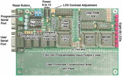
As for a candidate board that can meet the requirements of a smart module solution, see photo of the PJRC 8051 Development Board ($80 USD). It has 50 I/O lines, a serial interface, 30K of Flash Memory to store the programs, 32K RAM to buffer the EPROM data. It does not have a counter/timer function built in, but has a prototyping area large enough to hold a timer circuit if desired (and there is an expansion bus and uncommitted chip selects for adding I/O chips), the EPROM socket, a relay or switch to kick-in the 25V when needed, and perhaps room for a 25V regulator circuit to save an external power supply. It can get power from an 8-15V @ 500 mA power brick or a lab DC power supply. The board has its own on-board +5V regulator.

It comes with a monitor program safely stored in the 87C52 microcomputer to make it easy to develop and download user programs into the flash memory using the standard Intel Hex format (may be possible to use these routines to transfer the PET ROM data files into RAM for burning). It has an auto baud rate detector so the PC only needs to be running a terminal program at any baud rate.

The board would be programmed in the 8051 family microcomputer assembly language or I think there are public domain high level language compilers for this popular microcomputer.

Some questions I have are: What other candidate modules are available that meet the requirements? Is USB a better interface solution rather than RS232 (so modern PCs may be used) or is the interfacing software too difficult for an amateur programmer? What would be a good 25V regulator circuit that would fit?
Thanks,
Dave

PJRC 8051 Development board.
8051_board.jpg
 
Wow DaveM ! That seems like a really interesting idea. I don't have enough electronics knowledge to contribute much to such a project but if you get anywhere with it I'll definitely have a go at making one. In the mean time I have been looking through all my old stuff trying to find anything I can find to read these chips - but I'm getting nowhere. I've asked around locally at a few electronics places but no-one has anything to read these ROMS. Based on what I have learned from you guys it certainly seems most likely that one or more of these ROMS is causing a problem.

Harry:
Since I can't read the ROMS, if I sent them to you could you maybe try each in turn in a working PET to see which ones are good and which ones are bad? Of course I'll be happy to pay your costs for postage / time etc... by PayPal or something.

I presume this course of action is safe for Harry's PET?

Your motherboard appears to be the same as the 3032 machine, whch is no problem if that is the case , I have a working 3032, and checking out each rom would be no problem.
my 8032 which has recently had its mother board replaced,( thanks to Anders ) also has socketed roms , so I am sure out of the two machines , checking your roms should not present any problems. perhaps the consultants can confirm the 3032 board would be the correct way to go.
I did a quick check on the display with all the roms removed from the 3032, and yes the screen is full of garbage, and mixed characters, only diference seems to be your uf7 and uf8 are socketed , otherwise the boards looks the same. just pm me and I will do my best.
.....Harry
It looks like that 4032 is a 3032 by another name, but maybe you should compare your respective ROM numbers (they are all in the right place, right?).

Assuming they are the same you can of course just replace them one by one; if they're different and you have some way of transferring files to a PC then see Tezza's excellent writeup of how he read his ROMs in another PET and compared them to the images. Even if you can't transfer files, just reading a few bytes and manually comparing them will usually uncover any bad ones.
 
I’ve been putting some thoughts down about how to make a 2532 EPROM burner.
<snip>
Actually, programmers intended just for 25/27xxx chips are not too difficult to build; I built one for an AIM65 and another one for a PET and they were both not much more than one chip IIRC (but both those systems had digital I/O ports). The easiest way using a PC IMHO is to use a couple of binary counters to step through the addresses, using control lines for the counter clock and program pulse and the data lines for umm, data. Lots of interesting and simple circuits out there on the web...
 
dave_m;144244[SIZE=3 said:
The minimum smart module capability needed is 24 discrete I/O lines to output 12 bits of address, 8 bits of data and 4 control lines. A Counter/Timer chip would be handy to generate a precise 50 mS programming pulse, but this can be done a number of ways (hardware or software). There is need for a 25V Vpp programming voltage at 30 mA. The board would need to contain a 24 pin Zero Insertion Force (ZIF) socket to hold the chip to be programmed. There would have to be some software to create the required functions of downloading the 4K binary files to be programmed from a PC, a Program mode, a Verify mode to check that the part was correctly programmed, and maybe a Read mode to check unknown ROMs and calculate a sumcheck. [/SIZE]

Hi
It wouldn't take all that much to write a software loop to handle the timing. About the only thing I see you'd
need to add is the voltage level shifter for the programming voltage. A few resistors and a couple
transistors would handle that.
Dwight
 
Some questions I have are: What other candidate modules are available that meet the requirements? Is USB a better interface solution rather than RS232 (so modern PCs may be used) or is the interfacing software too difficult for an amateur programmer? What would be a good 25V regulator circuit that would fit?

Dave,

Great idea! I would certainly go for the USB option if possible. However, I have no idea how easy/hard this would be

Tez
 
Thanks Harry, I'll post my ROM numbers and positions later tonight and I'll pm you to organise sending them.

I'd still like to build a reader / programmer if possible - apart from anything else I'll need to burn some replacements for any bad ROMS Harry finds. Perhaps if we can come up with a solution that's relatively easy for a novice with basic electronics, soldering and programming skills we can keep even more PETs alive for longer ! Something that can be put together on a breadboard with the purchase of a couple of chips, resistors and transistors maybe - and some code they can download...
 
EPROM Programmer Research

EPROM Programmer Research

Here are some links that might help based on what I could find. (It seems much easier to search for 2732 based Programmer projects than 2532)

This one is for Atari Joystick ports:
http://www.atarimagazines.com/v4n8/EPROMBurner.html

This one started life on Amiga but has been adapted here for IBM Parallel Port:
http://www.dsaprojects.110mb.com/electronics/eprom/eprommer.html

Perhaps most interesting is this one which is also for IBM Parallel Port and has a great tutorial on EPROMS:
http://www.dxzone.com/cgi-bin/dir/jump2.cgi?ID=6262
This one has the software you can download from the site. Still looks a little complicated for a novice though !

Finally, my understanding is that you will need to make a small adapter to use 2532 in 2732 socket, like this:
http://www.pinballeon.com/truks/etechtips.htm


Perhaps we can simplify one of these projects a little more since our needs are purely for reading and writing the 2532?

;)
 
Here are some links that might help based on what I could find. (It seems much easier to search for 2732 based Programmer projects than 2532)

The approach for the PC interface looks good as it has done the part I dreaded, the Windows software, although I'm not sure if it would work on newer versions of Windows. You would only need to modify the wiring for the 2532 pinouts. Also the Vcc should stay at 5V and choose a Vpp of 25V.
-Dave
 
It wouldn't take all that much to write a software loop to handle the timing. About the only thing I see you'dneed to add is the voltage level shifter for the programming voltage. A few resistors and a couple transistors would handle that.

Dwight,
Yes I think you are right about the timing. I looked at the spec again and the tolerance on the 50mS is 10% so even my sloppy coding should be able to handle that.
On the 25V circuit, wouldn't I need a DC/DC converter or a regulator chip somewhere?
Thanks,
Dave
 
The easiest way using a PC IMHO is to use a couple of binary counters to step through the addresses, using control lines for the counter clock and program pulse and the data lines for umm, data. Lots of interesting and simple circuits out there on the web...

Mike,
Yes, I remember seeing your PROM burner for the PET. It is neat.
But for me, a hardware guy, I always think in terms of easy software development. What I like about the 8051 is how easy and fun it is to create a load file. It makes me a little queasy thinking about having to create an exe file for the Windows environment that will control the parallel port or any part of the PC hardware. I guess if I limit myself to DOS, it wouldn’t be so bad.
-Dave
 
Back
Top