• Please review our updated Terms and Rules here

8088 PC motherboard design

Soldering iron? For large boards, I use a heat gun and a galvanized bucket, holding the board with a pair of vise-grips and pulling things off (when required) with a pair of needle-nose pliers. Seems to get most of the large stuff just fine, but is hard on connectors and small components like resistors.

For small boards, I use an old toaster oven. Heat the board to about 350F, pull it out and bang it over the bucket.

I'd go nuts if I had to salvage stuff using a soldering iron.
i dont have heat gun, but it just takes a couple minutes to desolder a small IC using some copper braid.
 
Some people use a propane torch applied to the back side of the PCB--having the components facing downwards keeps them relatively cool. Some backwoods Chinese scrappers (where a lot of the "pulls" come from) use charcoal braziers. If you do either of these, do it out of doors--the fumes are something awful and probably not terribly healthful.
 
hmm, i've got the data lines hardwired to a HLT instruction ($F4 = 11110100) but the CPU still seems to be cycling addresses...... the DT/R pin from the 8288 is going directly to the DIR pin on the 72LS245 data transciever. CPU interface side on the 74LS245 is A. i have the DEN line from the 8288 going through a signal inverter (two of the pins on a 74LS04N) and then to E on the 74LS245. CEN on the 8288 is wired high. i'm very confused right now.

it also seems to keep cycling addresses if i attach a BIOS ROM from an old machine, although i've verified the ROM is sending out various different bytes of data depending on the addressing lines. (LEDs on the data lines, and i unhook and rehook the READY line to the CPU and i can see the data bus displays different bytes on every pause)

there is no DMA controller, PIT, or PIC connected to the circuitry so the BIOS running should halt the machine very quickly.

EDIT: also, there's no RAM involved yet so i'm not even using the AND/inverter scheme yet, i just have A0-A12 hooked into the ROM while i'm testing this.
 
Last edited:
I don't do well with words--a schematic of what you've got would help a lot.

BTW, you have grounded pin 33 on the 8088, haven't you?

i'll make up a schematic shortly, it's getting a little complicated so it'll take a few minutes to do. thanks for the help.

also, i dont have the datasheet in front of me this second, but if pin 33 is the min/max mode selector, yes it is grounded.
 
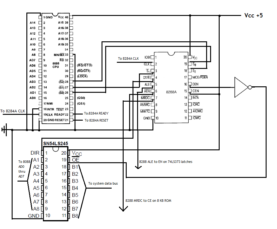
this is the basic wiring scheme for the stuff closest to the CPU:

8088schem2.png


a few notes:
-A0-A15 from the CPU are directly connected to the proper inputs on two 74LS373 latches. (no need for more addressing at the current time, just testing a ROM connection)
-ROM data lines are connected, of course, to the system data bus
-ROM addressing lines are connected to the 74LS737 latch outputs
-ROM's OE is tied low, and WE is tied high
-i have an odd issue with the 8088 NMI pin. if i tie it low OR high, the CPU seems to halt completely. and even stranger, even if i just touch a wire to it, with no connection on the other end, the same thing occurs! i've tried two different CPUs, so it's not a problem with them.
 
Stupid question, Mike.

Are you tying all unused input pins on the 8088 to defined logic levels? It's an HMOS chip; you can't leave them floating.
 
yes, i'd read about that previously. every unused input line is tied low. (checked the datasheet, the corresponding lines should be tied low in my current configuration) i have now noticed that i am getting consistent results with the NMI tied low or high, as it always halts at the same data byte on every reset.

i've used LEDs to confirm that the data lines always have the following pattern asserted onto them on halt: 00110000 (hex $30)
the address lines 0-12 are always: 1111111110101 (addr. 8,181 in the ROM)

i've got a dump of the ROM i'm using, examining in a hex editor, and the byte it stops it is actually the first byte of the BIOS date code, after the $EA jump instruction that should take the CPU to F000:E004. for some reason it doesn't like the jump instruction, or it's halting at the same location for another reason. at least i have been able to confirm that the correct data is asserted from the ROM based on the address.

maybe i should see what happens if i use minimum mode and keep the 8288 out of the picture for the moment. it shouldn't be halting until (obviously) the BIOS throws a HLT after it fails some test early on due to a lot of missing support circuitry that PCs have.

The 8088 Project Book should be showing up tomorrow, maybe that will give me some insight.
 
Last edited:
Well, not every unused input should be tied low, Mike. In particular, TEST/ should be tied high (through a resistor).

There's a schematic of a working 8088 board here that doesn't use an 8228. You might want to give it a try.
 
Well, not every unused input should be tied low, Mike. In particular, TEST/ should be tied high (through a resistor).

There's a schematic of a working 8088 board here that doesn't use an 8228. You might want to give it a try.

hmm, i didn't think TEST's level would matter if i didn't use the instruction that checks it and waits, so i had it low but i will try that and see what happens. very nice link too, thanks! i've got some 10-ohm and some 47-Kohm resistors laying around, but i'm going to guess those are way off on the value i want.
 
2K-10K is usual for this kind of thing. The 8088 is one of the easier old chips to interface, so I'm wondering if (a) your clock input is screwy or (b) your 8288 is bad or (c) you have power supply issues. A 'scope could solve these issues in a trice, but I suspect that you don't have one.

When dealing with MOS devices, always be suspect of inputs left dangling. Unlike TTL, MOS inputs can acquire just about any level, causing great havoc. Some modern microcontrollers provide an option for a built-in "weak" pullup (about 100K), for example.

i was considering the possibility that my 8288 is bad, because it gets QUITE hot. i know they can get fairly warm because they need to drive the entire system bus, but this one gets hot enough that it's hard to keep a finger on for more than a second or two. it was desoldered from my bad 5150 motherboard (one of the ones i got in that big haul i posted about a couple months back) and i'm starting to wonder if this chip was the problem with the system. i have a few more motherboards that dont work. i will see what happens if i use the 8288 from one of them.

my power supply is good i think. a multimeter reads 4.98 volts steadily, and thats while it's running the circuitry. it's the adapter from a parallel port ZIP drive, and can output 1 amp. and no i wish i had a 'scope. they can be far to expensive for me to consider. i was thinking of using an ADC circuit and using the parallel port on a PC with some proper software, but alas they can only really go up to about 100K samples/sec which isn't even close to enough for examining a circuit like an 8088-based computer.
 
hmm it's possible i need a few passive components on my clock circuit as well. i built that on a perf board though, not the solderless breadboard because i know sometimes those solderless boards can have stray capacitance. plus it gives me more room for the other stuff. do i HAVE to have a reset switch circuit connected? because i don't... the RESET pin does go to the CPU of course though.

i've simply got these connections on the 8284A:
-VCC tied to +5
-X1/X2 to 14.31818 MHz xtal
-GND/FC/AEN1/AEN2/CSYNC tied to ground
-RESET/READY to CPU
-CLK to CPU/8288
 
You either need a reset switch (debounced) or an RC network that meets the 8284 requirements. It's not critcal, but it does have to rise from 0 to logic high after power is applied. A 10 uF capacitor connected in series with a 10K resistor between ground (the capacitor end) and +5 (the resistor end) with the RES/ input connected to the junction should do it.

Otherwise, the 8088 can initialize in some very bizarre states.
 
When it arrives, can you tell me what the expected/prerequisite skill the book expects?
Still keeping an eye here, interesting stuff going on. :D

straight from the book "If you have some experience in digital circuit design and know a bit around programming--even BASIC programming--you'll feel right at home as you work your way through these pages. But if you think that CMOS is a Russian satellite or a JUMP is just an Olympic event, you'll have a hard time understanding the material covered in this book."

it also expects you to "have burned your hand on a soldering iron before" and honestly you dont need experience in digital circuit design. it explains everything very, very well. i will say though, that if you don't have any x86 ASM experience, writing the stuff for your ROMs may confound you a bit at first, but it does provide some example source code to use.
 
the breadboard 8088 definitely is working correctly now. one problem was the clock circuit wasn't robust enough, although it did work. it just wasn't stable. i eliminated the 8288 for now, and i'm working in minimum mode. i've got the memory map looking like this:

80000h - FFFFFh = 8 KB ROM (mirrored repeatedly in this range)
08000h - 7FFFFh = unused
00000h - 07FFFh = 32 KB SRAM

ive been able to verify it actually does run the code on the ROM correctly by putting an LED on the I/O control output of the CPU. if i burn an EEPROM full of NOPs, the I/O LED stays off. when i burn it full of OUT instructions, the LED stays on! i also burned a ROM that runs an idle loop 200,000 times, then a loop with OUT 200,000 and repeats the cycle continuously. when i run it, the I/O LED alternates on and off.

:rockon:

it's been running the double loop ROM for about 30 minutes now, no signs of locking up. i'm going to keep it on overnight and see if it's still going in the morning.

i'm done playing for tonight, but tomorrow i'm going to hook up a serial I/O controller, and come up with a little monitor (similar to the apple 2 monitor) and put that on the ROM so i can actually interact with it. also, turning this thing into a web server some day would be pretty epic...
 
Last edited:
Back
Top