• Please review our updated Terms and Rules here

Yet Another Pet Storage Project: (Pre-)Announcing the CBM4041

Twylo

Experienced Member
Joined
Feb 12, 2009
Messages
230
Location
Poulsbo, WA
Well, they're coming out of the woodwork now!

When I picked up my first-ever Commodore PETs back in May, I was unable to find any options for IEEE-488 based storage. Now just two months later, it looks like there are at least three ongoing. The more the merrier, right? :)

I have decided to go ahead with my original plans to produce a finished PET to SD Card product. It's now based on the sd2iec firmware. Nils Eilers did all the hard work of writing the IEEE-488 code and passing it back to Ingo Korb, who has merged it into the official sd2iec release. I've had a look at it, and it's very solid. I like Nils' coding style, it's well documented, and it looks like it will be easy to maintain. Plus, that means that I did not need to keep writing my own buggy firmware. Win-win!

I'm calling my hardware implementation the "CBM4041". The name is of course a play on the original CBM4040 drive, and I figure I'm safe from Commodore Business Machines lawyers here in the year 2011.

The CBM4041 is very heavily inspired by Nils Eilers' PetSD, but it is much less ambitious. The PetSD has a real time clock and an ethernet interface, the CBM4041 has neither. The PetSD has USB serial built in, the CBM4041 has RS-232 serial. It offers SD card storage, and that's all.

Of course it's not finished yet, but I have breadboarded it and I've done a first pass board layout. Now that I'm convinced that the design works well enough for my needs, I'm going to go ahead and get a very small run of Rev A boards made up.

Below is a video of the prototype in action, as well as the schematic and the first board layout. I'll do a final pass to clean up the board and prepare gerbers this week. Hopefully next week I'll get a beta or two soldered up.


cbm4041_brd.png


If my PET hadn't gone up in smoke again this weekend I'd totally want to get my paws on one of your first run of boards. I suppose the question now is how optimistic do I actually feel...
 
:)Did you overclock it too much:) How did it go up in smoke?

You can see my Thread Of Doom for details. I finally got my DOA PET 4032 to the point that it was running BASIC and seeing all 32k of RAM, but after being left on for several hours "burning in" with a BASIC ramtest program it spontaneously quit working again. It's probably just a reparable as the other four things I've already repaired, but to say the least it's annoying.
 
If my PET hadn't gone up in smoke again this weekend I'd totally want to get my paws on one of your first run of boards.

Oh no! :( I just caught up on your thread. Man, I hope it's just another minor fault and nothing serious. I'll respond over there with my own board washing tips.
 
I'm interested in a unit when ready. Been waiting for a good card-storage solution for a long time! Are you sure you want to call it 4041?
Wouldn't it be closer to the 9090 hard drives? Perhaps 9091 instead, or something catchy like IE3SD? (IEEE-SD)

BTW, Twylo... since you are using BASIC4 on the 2001 you might want to learn a couple handy commands...... CATALOG, DLOAD, DSAVE! ;-)
Or the short forms:
C<SHIFT>A
D<SHIFT>L"filename
D<SHIFT>S"filename

Steve
 
Last edited:
BTW, Twylo... since you are using BASIC4 on the 2001 you might want to learn a couple handy commands

I actually know about these, but I grew up on the Commodore 64 and those horrible BASIC 2.0 habits are so hard to break! My fingers just sort of know them...

OPEN 15,8,15:pRINT#15,"S0:BASIC2":CLOSE 15 ;)

-Twylo
 
I just got my first batch of prototype boards from Silver Circuits! Only five in the first batch (they threw one in for free) so I can debug and test.

cbm4041_pcb_rev_a.jpg


I already see a few things I need to improve on before I do the production run, so that will become REV B. For example, I forgot to add heat sink planes under the regulators :( A little copper and some vias to the ground plane on the other side should help thermal conductivity. I'll have to move some traces around but that's not a big deal.

Anyway, assuming that this works out and does the job, I'll start taking orders for kits later this week. I still need to work out pricing - it'll be just enough to cover materials and production. A kit will come with:

  • A board
  • The SD Card connector (since it must match the footprint exactly)
  • A pre-programmed ATmega 1284P
  • A 24-position card-edge connector for the PET (with solder eyelets)
  • Maybe a 24-pin IDC connector + length of ribbon cable, since the 24-pin IDC is not really standard and buying in bulk could save some cash

If you're not comfortable with surface mount soldering, I'll sell the board with the SD card already soldered on for an additional service fee (something like $5)

The rest of the parts you'll have to buy yourself, but they're all very standard and I'll have a list of part numbers for Digikey, Mouser, and SparkFun.

And, sorry, even though the kit will come with the parts for the cable, you'll have to solder the card-edge connector yourself, because I just hate making cables :)

-Twylo
 
I must say you've done amazing work on this! Im so impressed, I really want one! like really!!!!!!

Hi 90Q!

Thanks very much for the kind words! But really, most of the real work was done by Jim Brain, Nils Eilers, Ingo Korb, and others. They're the ones who made the software possible. I'm just building on what they've already accomplished.

-Twylo
 
And, sorry, even though the kit will come with the parts for the cable, you'll have to solder the card-edge connector yourself, because I just hate making cables :)

-Twylo

So, how about an option for eliminating the cable and allowing a connector on the board so the whole thing could plug into the IEEE port directly? Leave the pin header for those that want a cable solution.

Steve
 
Nice work, looking forward to more.

One problem with devices like this is that you need some convoluted adapters etc. if you want to connect another IEEE drive, printer, modem, etc.

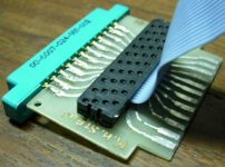
Adding In & Out through connectors to your board would probably complicate the layout too much, but maybe when you send in your next PCB order you could add a little transition board with male and female edge connectors and a header in between, sorta like this:
IEEEtransition.JPG
Maybe with a right-angle header your board could even plug in vertically; just watch out for the pin numbering.

Edit: Looks like while I was taking pictures ya beat me to it again, Steve ;-)
 
So, how about an option for eliminating the cable and allowing a connector on the board so the whole thing could plug into the IEEE port directly? Leave the pin header for those that want a cable solution.

I have given that some thought, and I'd like to make it an option. The hurdle has been finding right-angle, 0.156" pitch, 24-position, PCB mount card edge connectors. That would be my preferred solution, actually, I just haven't located any supply.

I'll do some more digging around this week to see if anyone has supply. If so it'd be a fairly simple redesign.

A few PET add-ons I have use a standard connector and mount it so the pcb is between the two rows. The pins are bent down towards the PCB and soldered on that way.

As for mike's idea... A pass-thru board could be made if the SD card connector is mounted on the side. This would also allow easier access to the card (IE: PET on desk against the wall.. no extra clearance behind is needed to change the card).

Steve
 
Adding In & Out through connectors to your board would probably complicate the layout too much, but maybe when you send in your next PCB order you could add a little transition board with male and female edge connectors and a header in between, sorta like this:

I really like that little board - it looks pretty vintage, but I could do exactly the same thing with hardly any problem. It wouldn't be very expensive either. I'll look into that.
 
I really like that little board - it looks pretty vintage...
Umm, yeah, 1981 as a matter of fact; one of my early attempts at making a PCB ;-)

I'd make it as short as possible to avoid excessive movement when a 'real' IEEE cable is attached; if you're not interested in connecting anything else you could just forget about the card-edge connector and it'd effectively just be a right-angle adapter that would let Steve put his PET as close to the wall as possible ;-)
 
Last edited:
Umm, yeah, 1981 as a matter of fact; one of my early attempts at making a PCB ;-)

Oh neat! I didn't think it was home-brewed, I assumed it was a commercial product from the early 80s. (or maybe it was one of your commercial products?)

I'm really late to the game. This is my very first commercially made PCB, yikes. It's been a pretty slow move from software into hardware :)
 
Kind words from a 'competitor' ;-)

How's yours coming along?

There's no competitors here! The more the better! :)

Don't forget Nils Eiler's PetSD, which looks really awesome. I hope he makes it a commercial product. The Ethernet and USB are sure to be fun for hacking. And there's Jim Brain's uIEC prototype with IEEE488. Neither is in production as far as I know, but I'd love to see five or six options out there.

It's awesome living in the future. Doing this isn't even expensive, just a little time consuming. Come up with a design, draw it up in Eagle or KiCAD, send off gerbers, and get a batch of boards back in a few weeks for less than a hundred bucks? I love it.
 
Back
Top