• Please review our updated Terms and Rules here

How to repair this TRS Mod I DDen adapter?

jharre

Experienced Member
Joined
Jun 12, 2009
Messages
151
Location
Placitas, NM
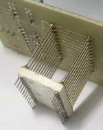
The ad said this Mod I Expansion Interface had an extra "memory board" when I bought it. Turns out it was a Tandy double-density adapter that should have been mounted in the socket for the WD1771. Unfortunately, it popped free during shipping and apparently bounced around quite a bit. All the pins got rather messed up as you can see in the picture.

Thought I could carefully straighten out the pins, but they are quite brittle and the first few broke right off even though I was very gentle.

The real solution seems to be to unsolder these and replace them, but I've looked around and can't seem to find the interconnect devices they used. They are pretty tall to make sure the board clears parts mounted to the EI board.

Does anyone know of a source for these - hopefully with a part number or part name?
TRS_DDen.jpg
 
It looks as if the bent pins belong to a socket (or socket strips) pushed onto the header pins.

"Round male header" or "Round female header" on eBay search will get you something that should work just fine, depending on exactly what you've got there. If it's really a socket with the bent pins, then the female header should be fine.

On the other hand, if it's really a socket pushed on, just pull the socket strips off and use as-is.
 

If in fact, that's what he's got. This actually looks more like a machine pin socket stacked onto the original adapter header, probably for protection. In that case, he can simply discard the socket. No need to add anything. or he could simply shove another machine-pin socket on after discarding the original.

We used to use machine-pin sockets on things such as ICE cable probes (you didn't want to have to repair one of those!) and ICs that were always being shoved in and out of sockets.
 
On the other hand, if it's really a socket pushed on, just pull the socket strips off and use as-is.

That's what I thought at first, too. Either its welded on, or the pins through it are one piece with a couple plastic strips mounted from the top and bottom - I sure couldn't pry it apart.

Thanks for that info, marmotking. At least now I know what I'm looking for.
 
Actually, they are one piece and each pin goes through the PCB, has a separator plastic block, which the pin goes through and the bottom part of the pin goes into the socket.

The only way to repair it is to unsolder the entire two strips and replace them.

I know, I had to do it many times when some customer would insist on installing the DDA themselves and bitched the pins.

Thanks for that info. At least the 40-pin socket for the FDC WD 1791 on the top of the board is just a couple strips - not a full-wide socket like the 1771 has. Makes it easier to unsolder the mounting pins.
 
The height of the connectors looks to be about 1/2". You might want to use a stacking PC B2B connector, such as those detailed on this page:

http://solutions.3m.com/wps/portal/...NF9B3C3SI1000000_nid=H4QFPP5KC3beWK7G49LP38gl

I'm guessing that the connector is that long to give enough height off the board to clear surrounding ICs.

You might get away with replacing the two strips by soldering a wirewrap 40 pin DIP socket to get the appropriate extension:

http://www.arieselec.com/products/12014.pdf
 
Last edited:
Got a couple of blister packs of individual ww pins (1/2" long) handy. If ya think they'll help I should have enough life left in me to drop em in the mail.

--T
 
Thanks Chuck and Terry.

I ordered what appears to be the last two Aries 20-0625-21 pin-line headers from Mouser today. Hope their inventory is right!

Terry, I'll be sure to let you know if the Aries parts don't work out - thanks for the offer.

<*> Jim
 
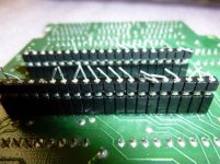
And if what Terry's got doesn't work, re-consider using the header+socket approach:

pins.jpg


Top of top pins to bottom of bottom pins = 5/8"
Top of top insulator to bottom of bottom insulator = 5/16"

If that isn't enough, you could stack another socket strip on that. A dot of solder will secure things.

I really like the socket strips--I don't have to go scrambling for oddball IC sockets--e.g. 22 pin 0.400" spacing that nobody carries. Just break off what you need.
 
Thanks Chuck and Terry.

I ordered what appears to be the last two Aries 20-0625-21 pin-line headers from Mouser today. Hope their inventory is right!

Terry, I'll be sure to let you know if the Aries parts don't work out - thanks for the offer.

<*> Jim
Hmm, I suspect that may not be what you want; they look like component carrier pins with forked ends to insert a wire, and they also look kinda short if I have the right picture in my mind.

Do I understand that it's a one-piece pin from the bent part right down through the PCB? Is the bottom plastic piece actually attached or do the pins just go through it?

If the Mouser parts don't work out you could always do it the way we used to do it back in the days before all sorts of versions of this sort of thing were readily available; here's a commercial PET ROM expander that uses straight pins (yes, the sewing kind) inserted through and soldered to the PCB, trimmed to the desired length, and then inserted and soldered to a machine pin socket which actually served as a plug:
PETromExp.JPG
 
And if what Terry's got doesn't work, re-consider using the header+socket approach:

Yup; I use a lot of those too, and in fact I thought that's what the item in question was; when I run out I often just cut them off normal machine pin sockets. Sometimes for something like this a socket is nice though (if it's actually standard spacing) to keep the rows aligned and supported.

If Terry's pins are really wire wrap pins they may be a little thick and permanently deform the socket, but I suppose in this case that doesn't matter unless you're going into a machined pin socket where they might not fit at all.
 
Last edited:
OK, the way this works is that there are 2 - 40 sockets on the adapter and two rows of 20 pin strip header which the appropriate signals from the two FDC chips (the original chip from the E/I board and the DD chip that comes with the adapter) go to which is then plugged into the socket that the original FDC came from.

One of the header strips is under one of the 40 pin sockets, so, you are not going to get a WW socket in there which is why they used the pin strip headers in the first place.

The pins go right straight through those plastic blocks which are there to keep the adapter from shorting to the E/I board by making sure that you can't push the pins too far down into the socket.

I have the service manual for the DDA and I checked the shadow mask just to make sure my memory serves me correctly.
 
Back
Top