• Please review our updated Terms and Rules here

Need help to get My pet 4016 work !

techtatan

Experienced Member
Joined
May 20, 2012
Messages
95
Location
france
Hi

I try to get work my PET 4016, i recently replaced the video board Assembly but it still does not work.
I was waiting to get an oscilloscope to make some diags!

so here is what happen :

there is no beep by start the computer, nothing on the screen !
i checked the voltages they seems to be OK !
i checked the 1Mhz clock on pin 37 and 39 on the CPU but there is nothing.
Next i checked Pin 6 on Ud3 and found 1.2Mhz.

The problem is that i do not own an other PET to invert parts. The ancient owner of the machine told me that the problem may result of a short circuit on PORT near to the DATASETTE port ? as far as he remember !

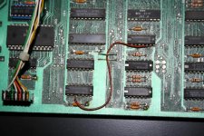
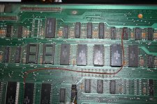
There are also some strange brown wires going from UB1 pin 3 to UC3 pin6 and UE6 pin 14 to UB13 pin 20 (see: photo)
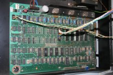
IMG_0199.jpg

So some help or advices where to start what points to check would be appreciated !


Kind regards, techtatan
 
Hi again

still need help !!!

are there some electronics gurus out there ???

thanks for any help

kind regards, techtatan
 
Hi, sorry you have not had a response. I think many of us take a vacation from computers in the summer. Read the thread on my 4016 repair and go through the steps that the guys suggested to me. That will be a very good start. It was only a couple months ago, and they helped me get mine working.
 
Yeah, sorry I missed your new thread; did you reply to Rory asking about your old video board?

Looks like you have the early version of the universal board; just to make sure we're looking at the correct schematic, what is the assy. number of the board?
 
Hi

Read the thread on my 4016 repair

I already looke at this post but did not own another pet to switch parts !
i may look again may be i missed something ;)

did you reply to Rory asking about your old video board?
I Pm him about !!!
just to make sure we're looking at the correct schematic, what is the assy. number of the board?

I will post back the info as soon as possible (i'm not at home now)
expect it for sunday !!

Thanks for reply,
Best regards,Techtatan
 
Yes, read through it again. Although I did do some parts swapping, there were a lot more troubleshooting steps that we went through, and none of those parts turned out to be defective. It turned out to be some bad ROM sockets and bad 4116 RAM chips.

My experience is still limited, but I'm starting to believe that it might be a good idea to replace ALL the sockets in these old machines. Those white ones in particular seem especially prone to having bad connections.
 
I checked the 1Mhz clock on pin 37 and 39 on the CPU but there is nothing.
Next i checked Pin 6 on Ud3 and found 1.2Mhz.
The old and new boards don't connect UD3 the same way; odd, your board looks like the old one, but ~1Mhz on pin 6 sounds like the new one.

In either case, you should have a ~1 Mhz signal on UE4/11, and that is connected to UE14/37 (6502 clk); sounds like there's a break in there somewhere. Check the 6502 socket.

Also check that the 6502's pin 40 is high.

Can you tell us exactly where those brown wires are connected?
 
Last edited:
Some thoughts on testing sockets...I don't know how others do it, but I've done this two ways:
1. Put the PBC on end and put one meter probe on the chip pin, and the other on the corresponding solder joint underneath. This method sometimes tricks you, because by putting pressure on both sides like that, you can make a connection that is otherwise broken.
2. The better, but more time consuming way, is to find where each pin connects to, and test between the chip pin and the "next hop" where the trace goes. That way I'm less likely to press together an intermittent connection with my meter probe.

In other news, unless it's a completely different board than mine, I noticed that your 4016 seems to have 32K of RAM in it.
 
...In other news, unless it's a completely different board than mine, I noticed that your 4016 seems to have 32K of RAM in it.
Indeed; looks like someone added the 8 sockets and chips.

Can we assume that this board was working as is and with those added chips at some point? I.e. the previous owner didn't make any changes trying to get it working?

No clock signal at the 6502 should be easy to track down.
 
Hi everybody

sorry for delay i just did not find time !

what is the assy. number of the board?

The assy N° is : 8032080

Also check that the 6502's pin 40 is high.

Sorry english is not my Native Langauge, so i do not understand wath you are meaning by "high" !

Can we assume that this board was working as is and with those added chips at some point?

Yes i think so ! the previous owner told me about a short cut on what i assume to be a IEEE-488 port !

the previous owner didn't make any changes trying to get it working?

He was thinking that the video assembly did not work ! he disassemble it and leave it like that in his attic for years ! somehow the video assembly get completly brocken in too much parts.

Can you tell us exactly where those brown wires are connected?

the first one goes from UB1 pin 3 to UC3 pin6
the second one goes from UE6 pin 14 to UB13 pin 20


IMG_0105.jpgIMG_0106.jpg

I hope i did not forget anything !

I will check sockets tomorrow and post back results !

Thank you all that much for reply ! :D

Kind regards, Techtatan
 
hi again

In either case, you should have a ~1 Mhz signal on UE4/11, and that is connected to UE14/37 (6502 clk)

there is no 1Mhz on UE4/11 and UE14/47

Check the 6502 socket.
I checked it and it need to be replaced 1 pin (10) seems to have contact problems ! I 'll look if i have a socket for replacement.

Can you tell us exactly where those brown wires are connected?
here are some additionnal infos :

UB1/3 is not connected to the motherboard ! only to the brown wire wich goes to UC3/6 that pin is connected to motherboard !
UB13/40 is not connected to motherboard ! only to the brown wire wich goes tu UE6/14 that pin is connected to motherboard !

Is that normal or not ?

My experience is still limited, but I'm starting to believe that it might be a good idea to replace ALL the sockets in these old machines. Those white ones in particular seem especially prone to having bad connections.

socket on UA3 is ok. and socket on ud7 is also ok !

I hope i will find time to check 8 ram sockets tomorrow ! i post then back !

Thanks you all again for reply and help !

Kind regards, techtatan
 
Hi

I changed cpu socket and UA3 socket (the white ones), I tested the 8 ram sockets they are ok !

I still encounter the same problem ! nothing on the screen no beep no 1Mhz on UE14/37 :confused:

Please can someone help/guide to next steps ? :rolleyes:

Kind regards, Techtatan
 
Hi
I changed cpu socket and UA3 socket (the white ones), I tested the 8 ram sockets they are ok !
I still encounter the same problem ! nothing on the screen no beep no 1Mhz on UE14/37 :confused:
Please can someone help/guide to next steps ? :rolleyes:
Kind regards, Techtatan
Sorry; I thought I had replied, but looks like it got lost somehow.

No offence, but we have no idea how much experience you have: do you have the correct schematics and can you read them?

According to the schematic:

http://www.zimmers.net/anonftp/pub/cbm/schematics/computers/pet/univ/8032081-06.gif

You should have:

UE5/6: 16Mhz
UD3/8: 16Mhz
UD3/12: 1 Mhz - This should be connected to UE14/37
 
Hi MikeS

No offence, but we have no idea how much experience you have: do you have the correct schematics and can you read them?

There is no offense in what you say. In fact, electronics is not my profession, i'm a computer technician and more used to work on recent computers and servers !
But vintage computers are really a passion of mine. I mean I grew up with a C64 in hand, so all these old computers represents a lot of memories for me.

So regarding electronics i'm a self made man, and my skills on reading schematics are a bit low ! But i have the passion it takes to learn and go through with it :D

According to the schematic:

http://www.zimmers.net/anonftp/pub/c...8032081-06.gif

You should have:

UE5/6: 16Mhz
UD3/8: 16Mhz
UD3/12: 1 Mhz - This should be connected to UE14/37

Sorry but the oscilloscope i have goes only till 8Mhz. So i can not test this now. I will try to get a better oscilloscope (this may take time) !

Is there a way to make some test for the moment without another osscilloscope ?
Where schould i start to search ?

Thanks a lot for reply , Kind regards
 
The frequency rating of an oscilloscope is not really a limit as such, merely the frequency above which the signals will appear distorted; we don't really care what the signal looks like, just where it disappears, so your oscilloscope may work anyway.

You want to follow the signal from the clock in the top left of page 6 (UE4/5 and UE4/6) through UE5/5 & 6 to UD3/8; there it gets divided into 8, 4, 2 and 1 Mhz signals and the 1Mhz signal from pin 12 should go to the 6502's clock input at pin 37.

Unless the schematic (or my thoughts ) are wrong, pin 6 of UD3 should be 8Mhz; are you sure it's really 1 Mhz?
 
Hi again,

I borrowed the oscilloscope from a friend at work and had to give it back for the weekend ! as a result I can not begin "investigations" ! :(
I hope he can lend it to me again on Monday evening.

Unless the schematic (or my thoughts ) are wrong, pin 6 of UD3 should be 8Mhz; are you sure it's really 1 Mhz?

the signal i got on UD3/6 is always between 0.800 Mhz and 1.2 MHZ ( I'm using a digital oscilloscope so normally i can not make any reading errors) !
I will check it again untill i have the oscilloscope again !

What do you think about the "strange brown wires" i found on the mother board ?

thank you very much for reply !
Good night if you are going to sleep !!

Kind regards
 
Hi again,

What do you think about the "strange brown wires" i found on the mother board ?
I haven't had the time to look for them on the schematic; can you find them and tell us what page of the schematics those IC sections are on?

Thanks.

Good night if you are going to sleep !!
Pas encore, helas; still have work to do...
 
Hi MikeS

sorry for the delay,

I tested the steps you guided me through and found absolutely nothing similar to what you explained and schematics you provided the link ! After checking several datasheets and the schematic i thought that's not possible.
So i checked the probe i had with the oscilloscope this one was bad ! really sorry for that !!

So I changed it and take through the tests again :
Unless the schematic (or my thoughts ) are wrong, pin 6 of UD3 should be 8Mhz; are you sure it's really 1 Mhz?

finally your thoughts according to what i found or vice versa :rolleyes: UD3/6 = 8Mhz

You want to follow the signal from the clock in the top left of page 6 (UE4/5 and UE4/6) through UE5/5 & 6 to UD3/8; there it gets divided into 8, 4, 2 and 1 Mhz signals and the 1Mhz signal from pin 12 should go to the 6502's clock input at pin 37.

UE4/5&6 = 16Mhz | UE5/5&6 = 16Mhz These are ok
UD3/8 =0Mhz | UD3/12 = 0Mhz these are not ok but : UD3/5&6&7 = 8Mhz | UD3/13=4Mhz | UD3/14 = 16MHZ | UD3/2 = 2Mhz .

Does this mean the SN74177N is bad ?

I did noot find time to look on shematics for the section concerning the "brown wires" I will do it as soon as possible ! :)

Thanks a lot and kind regards
 
Check your pin numbers:
UD3/14 = 16MHZ
UD3/14 must be Vcc (5V, 0Hz), not 16MHz; pin 8 (the opposite end) should be 16MHz.
UD3/5&6&7 = 8Mhz
UD3/7 must be ground (0V, 0Hz)

How about a list of what you see on all the pins of UD3?

And are you positive that you are looking at pin 37 of the 6502 and there is no signal there?
 
Last edited:
Hi again

I iverted the numbers !!!
while I was looking at them all this time on datasheet ! shame on me :confused:
sorry for this mistake i may need to get more sleep !

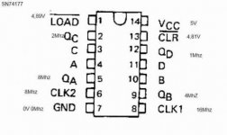
so regarding data sheet Link

UD3/1 = 4,89V | UD3/2 = 2Mhz | UD3/5&6 = 8Mhz | UD3/7 = 0V 0Mhz | UD3/8 = 16Mhz | UD3/9 = 4Mhz | UD3\12 = 1Mhz | UD3/13 = 4,81V | UD3/14 = 5V

SN74177.jpg

And are you positive that you are looking at pin 37 of the 6502 and there is no signal there?

Same mistake on this one ! I have 1Mhz on UB14/37.

sorry for this mistakes due to inexperience !

The problem of the computer still remains No Beep and Nothing on the screen !

Do you have any idea ? what should i check first ?

thanks for all, Kind regards
 
Back
Top