• Please review our updated Terms and Rules here

ST-225N termination pack

MerrickD

Experienced Member
Joined
Jun 22, 2011
Messages
104
Location
Santa Rosa, CA
I'm trying to get my ST-225N scsi drive set up for use on an ST02 controller and I'm having trouble getting the controller to see the drive. I noticed that my drive is missing the terminator packs and I think that might be causing the problem. I know that these terminator packs are supposed to be SIP resistors, but I don't know what resistance they are supposed to be. So two questions: Are these terminator packs necessary, and what type of SIP resistors are used on these kinds of hard drives?

thanks!
 
what type of SIP resistors are used on these kinds of hard drives?
Looking at the SCSI-1 devices that I have, the ones which require three by 8-pin SIPs use a common configuration.
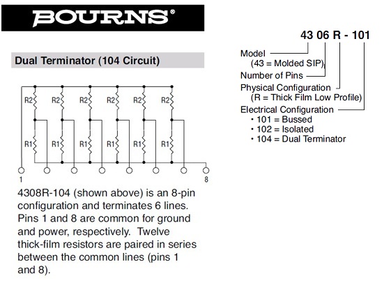
That configuration is as follows where R1 = 220 ohms and R2 = 330 ohms.

bournes_4308R.jpg


So the part number for the Bournes made unit would be 4308R-104-221/331

The 220 and 330 ohm values are standard for SCSI-1 (see http://www.interfacebus.com/Glossary-of-Terms-SCSI-interface-schematic.html)

The ST225N product manual quotes those values: "The ST225N uses open collector drivers. All signals are terminated with 220 to +5 VDC and 330 to ground. The terminating resistors are removable for multi-drive configuration."

I'm confident that the Bournes 4308R-104-221/331 (or equivalent) is what you need, but I think you should wait for confirmation.
 
SIP termination resistor packs for SCSI-1 drives come in two common flavors: 8 and 10 pin. Count the number of pins to be certain. The configuration of both is standard.

With short cables, in a pinch you can use a reasonable single-ended pullup; that is, 220 ohms only. It's not as effective as the 220/330 but in short runs to a single device, it's adequate for the slow speeds of SCSI-1.
 
Went to the local electronics store and they actually had the exact part that modem7 suggested. I went ahead and installed them but unfortunately the drive still isn't being seen by the ST02. ST02 is giving a "SCSI Host Adapter Failure" on boot. The floppy interface on the card is working though and I can bring up the ROM-based formatting utility, but it doesn't see the drive. I'm hoping that the controller isn't bad but I'm a bit concerned about that error.

thanks for the help so far, you guys have given me some really good info.

Edit: I hooked up the 225N to my Mac and it's working just fine.

Edit 2: I noticed that the ST02 controller has spaces where terminators could be soldered onto it. I decided to chance it and take the terminators off of the drive and solder them to the card. Now the drive is detected properly and it's working great so far.

Edit 3: Spoke too soon. I was able to low level format the drive using the ROM-based utility on the controller, but FDISK won't partition the drive for use. FDISK keeps giving me an error "no space to create a dos partition" after examining the drive for about 30 minutes (drive activity light comes on and the drive makes some noises every few minutes). Any ideas on what could cause this?
 
Last edited:
I do currently have terminators on both the card and the drive. The drive is being seen by the controller card, and I can low level format. I can't get it to partition with FDISK so the drive isn't usable right now. Strangely it does this whether terminators are installed on the drive end or not.
 
Could that be the INSTALLR.exe program that is mentioned? I haven't been able to find a copy of it online so far. I've been using g=c800:5 in DEBUG to bring up the built-in format program that is on the controller.
 
That's what I'm thinking. Have you tried using a utility to read and write physical sectors on the drive to see if it's even accessible?

What does FDISK say if you just ask it to display the partition information?
 
That's what I'm thinking. Have you tried using a utility to read and write physical sectors on the drive to see if it's even accessible?

What does FDISK say if you just ask it to display the partition information?

I can read and write to the drive using a disk editor. FDISK reports that there are "no partitions defined".
 
Try zeroing the first sector (cyl 0, head 0, sector 1) on the drive and see if FDISK likes that any better. If that doesn't work, I'll check the FDISK source and see what's up.
 
After zeroing out the first sector, FDISK can now create a partition. After the reboot the partition is apparently gone. Disk editor shows that some data has been written to the sector however. Not sure if it helps, but I noticed that the format utility in ROM writes hex 2C to every sector except the first one where it seems to do nothing.
 
Well yes, but how much data is written? Can you dump the first sector to show us?

And again, since I don't know what system this is, does your BIOS feature sector 0 protection?
 
Here is what the disk editor showed. The system is a generic 386DX board that I use to test PC hardware that I find (drives, controllers, video cards, etc) I've set up several other hard drives using this system on other 8-bit ISA drive controllers. If I can get the 225N and ST02 working together nicely they will go into an IBM XT. No sector protection as far as I can tell on this system.

Code:
Offset(h) 00 01 02 03 04 05 06 07 08 09 0A 0B 0C 0D 0E 0F
00000000  BA 33 80 8E 90 BC 00 3C 8B B4 10 07 10 1F BB BC  º3€Ž.¼.<‹´....»¼
00000010  BF 00 06 B9 00 01 B2 A5 AA 1D 06 00 00 BE BE 07  ¿..¹..²¥ª....¾¾.
00000020  B3 04 80 3C 80 34 0E 80 3C 00 35 1C 83 86 10 BE  ³.€<€4.€<.5.ƒ†.¾
00000030  8B 35 AF 8D 18 8B 14 8B 0C 02 8B AE 83 86 10 BE  ‹5¯..‹.‹..‹®ƒ†.¾
00000040  8B 34 1A 80 3C 00 34 B4 BE 8B 06 AC 3C 00 34 0B  ‹4.€<.4´¾‹.¬<.4.
00000050  16 BB 07 00 B4 0E 8D 10 1E AB B0 AB BE BF 05 00  .»..´....«°«¾¿..
00000060  BB 00 3C B8 01 02 17 8D 13 1F 33 0C 33 80 8D 13  ».<¸......3.3€..
00000070  0F 35 AD BE A3 06 AB 93 BE 82 06 BF BE 3D 81 3D  .5.¾£.«“¾‚.¿¾=.=
00000080  15 AA 35 87 8B B5 AA 00 3C 00 00 09 2E 36 21 2C  .ª5‡‹µª.<....6!,
00000090  29 24 20 30 21 32 34 29 34 29 2F 2E 20 34 21 22  )$ 0!24)4)/. 4!"
000000A0  2C 25 00 05 32 32 2F 32 20 2C 2F 21 24 29 2E 27  ,%..22/2 ,/!$).'
000000B0  20 2F 30 25 32 21 34 29 2E 27 20 33 39 33 34 25   /0%2!4).' 3934%
000000C0  2D 00 0D 29 33 33 29 2E 27 20 2F 30 25 32 21 34  -..)33).' /0%2!4
000000D0  29 2E 27 20 33 39 33 34 25 2D 00 00 00 00 00 00  ).' 3934%-......
000000E0  00 00 00 00 00 00 00 00 00 00 00 00 00 00 00 00  ................
000000F0  00 00 00 00 00 00 00 00 00 00 00 00 00 00 00 00  ................
00000100  00 00 00 00 00 00 00 00 00 00 00 00 00 00 00 00  ................
00000110  00 00 00 00 00 00 00 00 00 00 00 00 00 00 00 00  ................
00000120  00 00 00 00 00 00 00 00 00 00 00 00 00 00 00 00  ................
00000130  00 00 00 00 00 00 00 00 00 00 00 00 00 00 00 00  ................
00000140  00 00 00 00 00 00 00 00 00 00 00 00 00 00 00 00  ................
00000150  00 00 00 00 00 00 00 00 00 00 00 00 00 00 00 00  ................
00000160  00 00 00 00 00 00 00 00 00 00 00 00 00 00 00 00  ................
00000170  00 00 00 00 00 00 00 00 00 00 00 00 00 00 00 00  ................
00000180  00 00 00 00 00 00 00 00 00 00 00 00 00 00 00 00  ................
00000190  00 00 00 00 00 00 00 00 00 00 00 00 00 00 00 00  ................
000001A0  00 00 00 00 00 00 00 00 00 00 00 00 00 00 00 00  ................
000001B0  00 00 00 00 00 00 00 00 00 00 00 00 00 00 80 01  ..............€.
000001C0  01 00 04 03 91 23 11 00 00 00 3F A2 00 00 00 00  ....‘#....?¢....
000001D0  00 00 00 00 00 00 00 00 00 00 00 00 00 00 00 00  ................
000001E0  00 00 00 00 00 00 00 00 00 00 00 00 00 00 00 00  ................
000001F0  00 00 00 00 00 00 00 00 00 00 00 00 00 00 15 AA  ...............ª
 
Well, there's your answer. You're dropping bits. In particular, you're dropping bit 6. That 15 AA at the end should be 55 AA.

Let's look at the stuff at offset D0:

Code:
29 2E 27 20 33 39 33 34 25 2D

and add bit 6 to some of the bytes:

Code:
69 6E 67 20 73 79 73 74 65 6D

What's that spell? What's that spell? How about "ing system"?

Check your cabling, particularly the line for bit 6.
 
That's it! you nailed it. Cable checked out good so I took a closer look at the controller card. Found a broken trace right at pin 14 on the SCSI connector. A quick solder fix and everything is working as it should.

I really appreciate the effort, I don't know if I would've figured it out on my own.

Thanks!
 
Back
Top