• Please review our updated Terms and Rules here

PDP-11/44 Restoration

I am looking into it now. I may be a couple of days, but I may not. If I can get a high enough stand, I might actually be able to test the PSU using the cable going to the front panel.

I now have a stand that is tall enough for the PSU to sit on so I can use the front panel switch.
 
Last edited:
I now have a light bulb (reads 0.7 ohms), and am ready to test the PSU. I am able to use the front panel switch to energize it. I did a check between the 5+ and ground rails, and they read continuous. Is that a problem or is it part of the design because I know that some transformers can read continuous from live to ground.

After checking it some more, the problem seems to go away when the multimeter is connected for a few seconds, but there is resistance in the megaohm range. I am guessing that the complexity of this circuit could lead many possible paths. It almost seems like something is charging up which breaks the connection. When I connect the lamp, it reads continuous. I then disconnect it and the meter reads continuity for a few seconds before stopping. Just out of curiosity I measured the continuity between the flex print cables leading to the backpane (not attached to the PSU), and they read continuous.
 
Last edited:
Hey guys. The PSU works! I consulted someone I know about the problem that I noticed in the previous post. They told me that it was probably a capacitor charging that caused the continuity reading. The 5v rail reads a little over 6 volts when compared to ground. Is that within tolerance? Also how should I go about testing the other voltages present?

Thanks,
Old Computers
 
Yeah, you can't really test for a short over rails like that with a simple multimeter. So you now have a 500 lb curve-tracer :)
6V is way off spec.
Hook the multimeter set to amps between the light-bulb and the rail (series) and measure how much current you're drawing. Remember, you're shooting for 6A or more.
patscc
 
Would drawing less than the required current cause the voltage to be off? I'll test it later tonight and let you know what it reads.
 
Maybe. All I know the specified minimum load is 6.0 amps. There's also some remote sensing which we might look into, but let's make sure you're actually drawing at least 6.0 A first.
I'd not worry about the auxiliary voltages until the +5v leg is working properly.
It's good news that it hasn't blown up yet, though.
patscc
 
I just checked and it reads about 3A. I will source a bigger load for it. I think that that might be the cause for the higher voltage (after thinking about it I remember reading somewhere that the voltages will be off without sufficient load).
 
Thanks. I will report back when I get some more light bulbs. I also did a few more tests with the ammeter today. The PSU was on for less than a minute each test, but it has passed the smoke test each trial.

Do you know of a good place to get breakers identitical or similar to the ones DEC used? The one in the power distribution box is bad. I have to keep pressure on it for it to close (that's even without current). I do not like to do that too much for safety purposes.
 
I can't tell that yet because I am figuring how to remove the power distribution box from the cabinet. From what I can tell it is similar to the breaker on the PSU except it has three switches connected together instead of two.
 
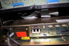
Sorry about the delay. Here is the photo.
IMG_0930.jpg

I also have some bad news regarding my VT101. I tested it out today, and I have found out that it will not receive characters from a DOS computer over COM1. It has worked in the past with that computer. I have tried different settings, but that does not help. It will transmit the characters though (FDD activates when I type dir). Should I post this in a new thread or is it okay in this one?
 
Last edited:
Okay. I will move that to a new topic. I have tested the loopback with the 20mA current loop and it passed, but I have not been able to test it with the RS-232 loopback yet.

So what do you think of the breaker in the power distribution box?
 
Sorry, I completely missed that photo.
Try removing them from the chassis. I'm interested in how the individual breakers are held together, screwed, or riveted.
You should be able to disengage the locking bar and figure out which one has the gamey spring.
patscc
 
Okay. I will try to do that soon.
I went ahead and posted the terminal question in a new thread.
 
Last edited:
I have managed to take apart the power distribution box. The breaker is actually three smaller breakers held together by a rivet. One of the breakers is good, the other two are bad.
 
There is a DEC 874-D for $60 and an older black 861-C for $30 over on EBay now, may be cheaper to buy a whole replacement power controller then trying to find and replace those breakers. All of the old power controllers for the PDP-11 stuff were basically the same so any will work, some were bigger than others but that’s about the only difference. Think the gold colored look better with the newer stuff and the black units with the old but that’s just me.
 
Back
Top