• Please review our updated Terms and Rules here

Mechanical Keyboard - electrical issue?

RickNel

Veteran Member
Joined
Apr 24, 2009
Messages
641
Location
Canberra, Australia
For a project, I've re-wired the switch matrix of a vintage mechanical keyboard (from a serial terminal) to match the switch matrix of an AT keyboard, based on the Intel 83C51KB controller. According to the Intel datasheet, the controller chip has internal debounce circuitry, so I followed the original membrane matrix pin for pin, 8 KSO x 16 KSI, leaving out redundant switch points and re-mapped to the key combinations.

When connected to a PC, most keys are read correctly but about 25 keys produce either two characters or an unrecognised code. The character pairs are always the correct (re-mapped) character plus another character that shares one of the same address lines, either KSO or KSI. They are never adjacent characters in the matrix, but separated by four or five lines. There are no shorts or dry joints within the matrix.

One thing I have noticed is that the original printed membrane circuits exhibit a small resistance factor between switch and connector, from 3ohms up to 12ohms for the longest traces. My re-wired mechanical matrix uses transformer winding wire and resistance never measures above 1.5ohms, usually .8ohms. I'm wondering whether that higher resistance in the membrane circuit might have functioned to stabilise the scanning signals as some sort of pull-up.

I've also noticed that the membrane circuit has a little 1cm extension twig at the far end of each printed matrix line, which doesn't connect to anything. I'm wondering if those twigs create some sort of terminating capacitance to the earth mat printed under the bottom membrane.

Advice sought how to condition the keyboard signals appropriately, or any other causes for the controller misreading key switches.

Rick
 
Each switch holds a pair of copper alloy vertical blades tensioned to be in contact, but held apart by a plastic crosspiece when the key is in the raised position. The key is supported on a coil spring that surrounds the connection mechanism.

The keyboard originally had what I think were capacitors of a few pF value in series on each matrix line, often more than one per line and located at each point where there is a junction in the PCB trace. Most had decayed and I'm not confident that my multimeter has measured the surviving ones accurately, so currently they are all removed and the rewired circuit runs direct to controller.

I've not previously seen capacitors used in series like this - smoothing caps are usually across the circuit. So I wonder if these are actually resistors and the pF values are just measurement error. They are brown cylinders with a single green belt, either tantalum or some weak ceramic that crumbles easily. The leads penetrate less than 1mm into the ceramic and break off with the lightest pressure.

So how would I decrease the bounce factor from the switches? Restore caps in series? What sort of value?

Rick
 
Last edited:
Are you certain that those were capacitors and not diodes?

Definitely not those ones. No polarity, and continuity tests in both directions as with other capacitors, initial resistance value reduces to zero within 1 sec. This is the specimen:

KeboardCap.jpg

However, the original keyboard circuit has diodes on three of the 8 KSI lines. Those lines cover the keys that might be held down in a two-key strike - SHIFT, CAPSLOCK, and CONTROL. I guessed they were not for general bounce suppression so bypassed them. The current issue is not related to two-key situations.

At any rate, an RC network on each sense line might debounce things sufficiently.

To clarify, by "sense line" do you mean the 8 x KSI lines? Scope shows me these KSI are normally stable high at 5v, while the 16 x KSO lines pulse low, at what I assume is the scanning rate. So, can I apply RC networks to KSI lines taking the key switches as source and the controller chip as sink? Or, since it is the KSO lines that pulse low, do I have to put RC networks across those lines, instead or as well as the KSI. The RC circuits I have looked at are to stabilise an output moving to logic high. I've been studying the controller datasheet but can't work out whether the sense input lines are active high or active low.

Rick
 
The KSI lines. A RC debounce will tend to smooth out the bounces. The trick is to make sure that the RC time constant is smaller than the maximum rate at which keys will be hit.

I'm also assuming that both the driving lines and the sense lines aren't overly long (<12", say).
 
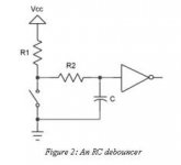
From what I have found online, the standard RC debounce circuit would look like this:

RC+inverter.jpeg

It assumes output via an inverting gate. I don't want to add 8 inverter circuits to this project if I can achieve the debounce in analog. Plus I believe I need output high to the 85C51KB controller. Am I mistaken about that?

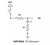
For logic high output, I'm thinking of an RC circuit that charges the cap on keypress. On key release, the cap discharges to ground via bleeder resister.

RC- no inverter.jpg


Is this worth testing or is there a simpler solution?

Rick
 
Curious; how would key bounce consistently give you two different keys? I don't suppose it could be crosstalk?
 
Crosstalk was my first guess, but since this whole thing is basically an 8051, a glitch from contact bounce could make for some interesting decoding. Trying an RC filter might help. Using some external pullups might also help.
 
After all, it was crosstalk. I tested some RC configurations and values on lines that were showing errors, and there was no improvement (some values made things worse, of course).

So I went over all circuits with higher magnification and found a number of shorts. The new wires make quite a ratsnest and there were two places uninsulated wire contacted solder points on another circuit.

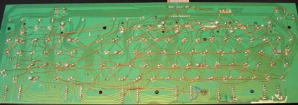
In addition, I found spots where my cutting of the original traces on the PCB had left a fragementary connection, which was enough to short the signals. Here is final physical wire matrix, over trace-cut PCB.

PCD Matrix remap.jpg

Also, I found that the 83C51 does not pass through any scan code for a matrix address that does not match it's internal translation map. Row/column switch addresses that are vacant in the OEM's ROM table cannot be used. I had tried to use some vacant addresses for keys that do not appear on the Honeywell AT keyboard, such as RESET and PRINT. This can only be achieved by mapping to some unwanted AT key (eg Numpad +) for hardware remap, then re-mapping again in software such as ansi.sys.

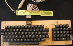
The good news is that the debounce routine in the 83C51KB is quite robust enough to handle whatever my mechanical switches throw at it. Presumably it could be used for all sorts of electro-mechanical control applications. The Soroc keyboard now produces the expected scan code from every switch.

Soroc to PS2.jpg

A second level of re-map has to be done in software to correct different shift and ctl combos and implement ANSI terminal escape sequence keys. I'll blog about the project when I get the software translations sorted.

Rick
 
Isn't the 83C51 just a pre-programmed 80C51? It seems that you could avoid the hassle of double-level translation and just program your own 8051 (or whatever microcontroller you desired).
 
It seems that you could avoid the hassle of double-level translation and just program your own 8051 (or whatever microcontroller you desired).

I'm sure it could be done, but the hassle factor is hard to compare. I'd be interested to know if anyone has done it on this type of chip. The microcontroller has several tasks - running the clocked scan routine, translating >200 returnable addresses to scan codes, doing the serial communication to the AT/PS2 port, controlling keyboard LEDs... Not sure I would like to write all that from scratch, but might consider modding a model code set if such a thing existed.

Because this project is emulating an ANSI terminal, I am already using ansi.sys to translate ~16 single-byte scan codes off the keyboard to multi-byte ANSI escape sequences at the PC, so it is not too much hassle to add the <30 translations for different key/shift/ctl combinations. Currently debugging first pass at that.

Rick
 
Back
Top