• Please review our updated Terms and Rules here

Commodore PET 2001-32n - Video/boot problem

dhoelzer

Veteran Member
Joined
Oct 20, 2012
Messages
523
Location
New York
Good morning!

I recently rescued a 2001-32n that had a family of mice living in it for quite a long time. After finally removing all of the carcasses and about a pillow's worth of bedding, I've pretty much got everything cleaned up and back together.

Following cleaning, I checked it over and plugged it in. It powers up just fine (wow) but I have a little problem. Let me describe the symptoms:

When it tries to start, it drops into the monitor with the PC at D379 and the SP at F6. At first I thought it might be a corrupted eprom, but every now and then it will actually halt at a different instruction.

Additionally, there is some kind of corruption going on somewhere. At the bottom of the screen there are 5 columns of zeroes spread out across the screen in a pattern as pictured below. You can sort of see another artifact that really looks like something's crossed somewhere.. There is a sort of "ghost" of these columns offset up and to the right. The ghost columns are scanning bottom to top, looking like some kind of clock line is crossed somewhere.

If I fill the screen with "A" you can see that various positions are corrupted to "Q". Where would you guys start?
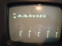
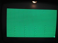
photo copy.jpgphoto.jpg
 
Hello,

I'd suggest checking the ROMs with regard to the monitor entry at startup. Although you are seeing various PC values, such behaviour is still possible with a dodgy ROM.

The video RAMs are the most likely cause of your display problems. If the A to Q problem only happens when the screen is filled then video RAM, otherwise character ROM.

Cheers
Robin
 
Last edited:
Hello,

I'd suggest checking the ROMs with regard to the monitor entry at startup. Although you are seeing various PC values, such behaviour is still possible with a dodgy ROM.

The video RAMs are the most likely cause of your display problems. If the A to Q problem only happens when the screen is filled then video RAM, otherwise character ROM.

Cheers
Robin

I'm working on breadboarding something to read these chips. Nothing I have will read a 2532 as is.

As for the video RAM... That was my thought as well, but when I try to "pinch a chip over a chip" trick it makes no difference at all. As you can see in the pictures, when the screen isn't filled those positions have zeroes in them, so it really does seem that something's latched or shorted somewhere.
 
I'm working on breadboarding something to read these chips. Nothing I have will read a 2532 as is.
What have you got? Various machines use a similar pinout, and of course they're almost the same as a 2732 or even a 2716 with a couple of sockets and a little jumpering. If the monitor is working correctly you could use it to spot check a few ROM locations as Robin suggested; that'll usually find stuck bits and/or addressing issues.

As for the video RAM... That was my thought as well, but when I try to "pinch a chip over a chip" trick it makes no difference at all. As you can see in the pictures, when the screen isn't filled those positions have zeroes in them, so it really does seem that something's latched or shorted somewhere.
I assume they're not in sockets? Nice when they are since you can just swap them.

And the usual tedious question that we have to ask since you didn't put it in your profile: where are you?
 
What have you got? Various machines use a similar pinout, and of course they're almost the same as a 2732 or even a 2716 with a couple of sockets and a little jumpering. If the monitor is working correctly you could use it to spot check a few ROM locations as Robin suggested; that'll usually find stuck bits and/or addressing issues.

I have an old Willem for which I have no parallel port to connect it to, so I'm building something. The monitor is working mostly ok. Dumping ram is fitful. Sometimes it will dump RAM sometimes it wont. When it does, it did successfully dump M 0000,FFFF, though it must have looped in there somewhere since it only has 32k. Still, it did not die half way through.

I assume they're not in sockets? Nice when they are since you can just swap them.

They are not.

And the usual tedious question that we have to ask since you didn't put it in your profile: where are you?

I'm really not sure how that can help you to troubleshoot, but I'm in New York.

Thanks!
 
If the monitor is working correctly you could use it to spot check a few ROM locations as Robin suggested; that'll usually find stuck bits and/or addressing issues.

I don't have a clean dump of these chips to compare anything to. Here's what's in the PET:

901465-01 - UD-6
901465-02 - UD-7
901447-24 - UD-8
901465-03 - UD-9
901447-10 - UF-10

Any recommended values to look at?
 
I hate it when I answer my own question...

So, the $c000 ROM seems to match the dump on Zimmers as best I can tell. It's rough with corrupt characters floating around, but it looks good.
The $d000 ROM seems to be filled with a D0 pattern... that doesn't look good. ;)
A quick peek at the first few bytes of the Edit ROM at $e000 looks good too through the corrupted characters.
The Kernal at $f000 seems readable as well.

I can't seem to locate a reference that documents the memory location of the character generator ROM. Where is that exactly?

Finally, based on the above, would you assume that the UD-7 eprom is corrupted or that there's something shorted on that socket?

Thanks!
 
Definitely looks like a problem with UD7; reading D0 suggests that it's effectively not there at all. Check for continuity (using the actual IC pins) between UD7-20 and UD2-15, as well as between UD7-21 and UD7-24 (and check power and ground of course). Is it soldered in as well, or can you pull it and stick it into one of the spare sockets?

The CG ROM is not in the memory map, it's addressed by the video RAM data; too bad your Willem's not working as it's a JEDEC standard 2716.

There's a simple adapter in one of the older threads here that lets you read & program a 2532 in a 2732 programmer socket (an IC socket or two, a couple of diodes and a jumper IIRC); an adapter to use a 2732 in a 2532 socket is even simpler and even commercially available for ~$5.00

The reason I asked about your location is that if you were in Toronto, for example, I'd happily volunteer to come over with whatever parts or equipment to help you out, and I'm sure many others would do the same if they read that you were in their home town or close to it.

And of course if it comes to mailing parts which it ultimately often does, it makes a difference whether you're in New York or in Melbourne, Australia; in cases like that I don't even reply if I have to ask.

Let me ask you: why don't you proudly display where you are? What's the deal?
 
Last edited:
Definitely looks like a problem with UD7; reading D0 suggests that it's effectively not there at all. Check for continuity (using the actual IC pins) between UD7-20 and UD2-14

Mike,
Good things to do. But there is a pinout typo in your SEL D chip select. It should be continuity between UD7-20 and UD2-15.

If there is good continuity, then I agree that the chip may be bad. I would be glad to send a 901465-02 EPROM to the person in NY to help get a PET back on the air.
-Dave
 
Mike,
Good things to do. But there is a pinout typo in your SEL D chip select. It should be continuity between UD7-20 and UD2-15.

-Dave
D'oh! I even double-checked it; I blame the cheap dollar-store glasses ;-) ... Correction made.

Thanks, Dave!
 
Bad Chip?

Bad Chip?

Sorry about the lack of a location there. It's my inherently paranoid nature. I'll add NY to my profile. ;) What you said makes a lot of sense.

Mike,
Good things to do. But there is a pinout typo in your SEL D chip select. It should be continuity between UD7-20 and UD2-15.

Continuity exists! I suppose that's a good sign. For good measure I double checked and that socket is also receiving power and has a good ground, so it looks like it's just a bad chip.

If there is good continuity, then I agree that the chip may be bad. I would be glad to send a 901465-02 EPROM to the person in NY to help get a PET back on the air.

Wow, that would be super! If you'd like, I have a stack of 2532s here. I'd be glad to send one your way so as not to diminish your own supply. I'm still weeks away from having the time to build a burner. I'd love to use my Willem, but the lack of a parallel port on anything I own is going to really hamper that. ;)

As great as this is, I'm still puzzled by the zeroes and the ghosting. Perhaps I'll desolder the 2114s and put in some sockets as well as some new chips and see what that does for it.

Thanks!
 
Last edited:
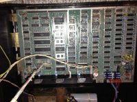
Oh, and by the way... I did find pointers to schematics but had trouble figuring out which set were actually my PET. Could someone point me at what seems like it would be right for a 2001-32n with Basic 2 ROMs? I'm attaching a photo of the board to assist. Thanks!

photo.jpg
 
Actually, continuity is a bad sign, since that means it's not just a simple corroded or broken trace that's easily jumpered.

This should be the schematics etc. for your board:
http://www.zimmers.net/anonftp/pub/cbm/schematics/computers/pet/2001N/index.html

I see that the ROMs are socketed (now that I think about I think they were in all PETs up to the CRTC Fat 40 & 8032 boards). Just for fun, stick the D ROM into one of the spare sockets; use UD3 and use the monitor to dump 9000H onward and if the ROM's really bad you'll probably see all 90s.

As to the video, it's not really a simple 'classic' RAM symptom but considering how notoriously unreliable they were I'd still replace or at least swap them.

How are your soldering skills, and have you got any test equipment other than (presumably) a multimeter?
 
Actually, continuity is a bad sign, since that means it's not just a simple corroded or broken trace that's easily jumpered.

Good sign meaning that the source of the trouble has been identified. ;)


Excellent! Thanks!

I see that the ROMs are socketed (now that I think about I think they were in all PETs up to the CRTC Fat 40 & 8032 boards). Just for fun, stick the D ROM into one of the spare sockets; use UD3 and use the monitor to dump 9000H onward and if the ROM's really bad you'll probably see all 90s.

As predicted, all 0x90.

As to the video, it's not really a simple 'classic' RAM symptom but considering how notoriously unreliable they were I'd still replace or at least swap them.
How are your soldering skills, and have you got any test equipment other than (presumably) a multimeter?

Rusty but more than adequate. Though I rarely get the iron out these days, I used to build, maintain and repair arcade and pinball machines back in the 80s.

Thanks again!
 
Last edited:
As to the video, it's not really a simple 'classic' RAM symptom but considering how notoriously unreliable they were I'd still replace or at least swap them.

Mike,
I did notice that in the first photo, a zero character ($30) is appearing in place of a space ($20) and in the second photo, a 'Q' ($51) is appearing in place of an 'A' ($41). So it looks to me like screen data bit 4 (SD4) is dodgy. This points to a suspect Video RAM F7 pin 14. I would replace this one first.
-Dave

Thanks, that's super great advice!

Actually, I pulled out both chips and soldered in sockets, put in the new SRAM and the screen was beautiful... for about 30 seconds, then it went bananas. I apparently have a cold solder joint somewhere and I suspect it's on the top side. I'm really not looking forward to trying to get those sockets back off. :)
 
What does "bananas" look like?

I'm currently in London and a bit of a distance from my PET. I'll let you know when I get back home.

From memory, the entire screen filled with stuff. Was it random stuff is the question.. That I don't recall. It was interesting that when powered off and back on the screen was filled with a static character during "POST" but then went bananas again. I've had a few seconds of clear screens here and there since. My thinking was it had to do with fiddling with the sockets, but thinking now I wonder if there's a 74XXX chip selector that wasn't happy with my soldering.
 
Back
Top