• Please review our updated Terms and Rules here

AT to XT Keyboard Converter

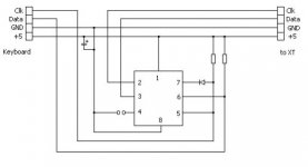
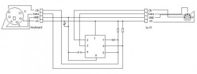
Mine isn't as elegant. Almost 2 years ago in July, I threw together this DIN to PS/2 keyboard adapter because I wanted to go old skool with one of my old keyboards, plugged into my computer's PS/2 port. They use the same protocol. The only difference is in the pin layout. I looked for the original picture that was much higher in resolution, but I wasn't able to find it. I was only able to find this one. Hopefully you can discern the wire connections.

In this case, not relevant, I think. PS/2 or AT keyboards use a different scan code set and protocol from the 5150/5160 keyboards, which implies that you need some intelligence there. There are a few PS/2 style keyboards that still retain the ability to recognize the XT protocol, but they're getting very rare.

Simple mini-DIN-to-DIN adapters are a commodity product--I've got a box full of them that go both directions.
 
Hi
I still have a bunch of these PCBs left in case anyone wants one or more.

Thanks and have a nice day!

Andrew Lynch
 
Hallo allemaal,


I built one myself and it works very fine except at one point. I use it with a XT equiped with the XT-IDE card. This card uses the new Universal BIOS V2.0.0.

The problem: after a Ctrl-Alt-Del the menu won't react on any key except that that the counter at the bottom of the menu disappears. But if I apply a reset, the menu works as it should. Neither the PIC nor the keyboard have a connection with the RESET line. It happens with both the original UNITRON BIOS of that board as with my own self programmed one. And my own one only skips checking the memory after a soft reset. The only device that could notice the difference is the hard drive itself but that is a bit far searched IMHO.
Any comment?


Groetjes, Ruud Baltissen
www.Baltissen.org
 
try tapping the ctrl or alt keys a couple times when it is stuck at the menu.
I have seen this as well, although not 100% of the time, where the status of the alt or ctrl key is stuck. When stuck, the menu doesn't appear to respond, but it is merely getting confused with Alt+down as a keystroke instead of just down. Tapping the key a couple times seems to refresh the true state of the keyboard and then everything works as expected.
 
Hi
There are three of the AT2XTKBD PCBs left in case anyone would like some. They are $5 each plus $1 shipping in the US and $3 elsewhere. Please send a PayPal to LYNCHAJ@YAHOO.COM and I will send your board(s) right away!

Thanks and have a nice day!

Andrew Lynch
 
Hi, i have done this project, but mine 8088 computer tells me
-Keyboard error 02FF
and makes beeps every time i press any of keys and release, like double beep.. do you know what might be a problem? tryed with jumper and without...
thnks
 
sure man, and it's burned in a right way, making internal oscillator with iogp4 and iogp5 as io... wdt, mclre disabled... anyway without any firmware (empty chip) signals will not flow from KB to computer, and as i see computer beeps, so he receives something..but wrong?
my KB chikony KB-9810, very common keyboard without any outstanding features.
just for sureness can you post your HEX? but .. i don't know when i compiled it there were no errors...
 
Last edited:
Okay, this one's out of my archive. Not to be too awfully stupid, but you don't have your ins and outs confused here, do you?
 

Attachments

  • xtathex.zip
    1.2 KB · Views: 5
aagghhh your hex and mine are fully indentical :( i checked it in a total commander with "check by content" function :(
all of yours schematics are drown in a little complicated way (sorry) so i just redraw it in my way here
XTATkey.jpg
all of you can use it if you want , my gift lol kiddin

anyway, i use 2.2k for resistors, 1n4148 diode.... three capacitors in a parallel 100nf, 220mf and 1mf tantalus :) more than enough...
if i just had oscilloscope..

STOP.. your included pdf schematic... look, ackording to manuals the TOP pin of xt keyboards, the middle one, is DATA pin, and your manual does not use it at all..
i don't know what it might be, but my keyboard switchs three leds (numlock, caps, scroll) in a right way, when i press one of those the led brings itself ON and OFF, i think it weren't be possible if clock and data where messed..but beeps every time i press and release them
do you think i just have to forget the original pinouts and connect it in your way?
take a look http://www.allpinouts.org/index.php/Keyboard_XT_5_pin
why pinouts in your pdf are diffres from anybody's else?

sorry for my complicated language :) i appreciate your attention!
 
aagghhh your hex and mine are fully indentical :( i checked it in a total commander with "check by content" function :(
all of yours schematics are drown in a little complicated way (sorry) so i just redraw it in my way here
View attachment 11705
all of you can use it if you want , my gift lol kiddin

anyway, i use 2.2k for resistors, 1n4148 diode.... three capacitors in a parallel 100nf, 220mf and 1mf tantalus :) more than enough...
if i just had oscilloscope..

STOP.. your included pdf schematic... look, ackording to manuals the TOP pin of xt keyboards, the middle one, is DATA pin, and your manual does not use it at all..
i don't know what it might be, but my keyboard switchs three leds (numlock, caps, scroll) in a right way, when i press one of those the led brings itself ON and OFF, i think it weren't be possible if clock and data where messed..but beeps every time i press and release them
do you think i just have to forget the original pinouts and connect it in your way?
take a look http://www.allpinouts.org/index.php/Keyboard_XT_5_pin
why pinouts in your pdf are diffres from anybody's else?

sorry for my complicated language :) i appreciate your attention!
 
yours pinouts driving me super crazy!!!! the middle one (third)on XT connector are DATA pin, two pins around it are + and -, why your pdf schematic don't uses middle one at all!?
 
haha I can see how that happened.

It's been drawn with the pin numbers sequentially, but on the actual DIN plug they're numbered different. In the schematic the visual symbol indicates pin 3 is the middle one, but on the actual plug it's the pin on the far side - Keyboard Reset - which isn't needed.

Ignore the visual aid of the DIN connector from the scheamtic, and work off the pin numbers.

The number-to-pin map can be seen here: http://www.allpinouts.org/index.php/Keyboard_XT_5_pin
Notice the pin numbering around the connector. 1-4-2-5-3
 
Last edited:
i wish be killed but here is a full schematic i used, all sleepless night with a stupid most simplest circuit in the world i can't get it the work :((
XTATkey.jpg
 
Last edited:
Well, I don't think I authored the schematic--I think Andrew did it. It was simple enough for me just to remember how the thing was wired up from memory. I take it that you're not using one of the PCBs that Andrew ran up? Either he or Hargle probably has the artwork for it.
 
Back
Top