• Please review our updated Terms and Rules here

8032 issue and PET character ROM vs EPROM

giobbi

Veteran Member
Joined
Dec 23, 2012
Messages
987
Location
São Paulo country, Brazil
Hi,

I have some trouble fixing an issue on my 8032 spare computer. Some days ago it was showing wrong chars at boot; slowly, a messed start screen became normal, as something cleaned the screen from garbage and changed strange symbols with the right chars (I don't know how to describe it better)...

Since I used this machine as spare parts during my previous 3032 fixing, I pulled out all basic ROMs and I also extracted and put back again on socket two chips (UE13 and UE14, 74LS10 and 7425). ROMs worked fine on 3032. I can't say about 74LS10 and 7425 since I haven't a spare replacement (yet).

Now I put all parts in the right place and I switched the computer on, just to discover that nothing appears on the screen (black screen, no garbage, no vital signs on the CRT, but the tube grid is red). The buzzer rings at boot, so at least it's detecting kernal and edit ROMs (I discovered you can extract BASIC ROMs and it still rings).

I've also checked the system with the Nicolas Welte's RAM/ROM adapter so definitely shouldn't be a ROMs problem (except for the char ROM socket).


Is there any test I could do without a scope to detect if the problem is a crt issue or mainboard issue?


A future question about the char ROM: using a 2732, should I program it at specific address (i.e. $0800 as I did with the edit ROM) ?

-- Giovi
 
Last edited:
It's definitely a CRT assy problem...

It's definitely a CRT assy problem...

Finally I got back the other 8032-sk I lent to a friend; this way I was able to check and discover that the problem is the CRT, indeed.

BUT.... I have zero knowledge about CRT assy (except the fact that electrical shock from a CRT board is quite painful -I've learnt the lesson when I was 12 and I still remember ;-) ), so I don't know what to do.

I already tested the brightness pot and it's working. I also checked others pots, just to be sure, but apparently they aren't culprits; well, at least nothing changes if you regulate them.

I just have some clues (maybe irrilevant):

1) Switching the CRT on when it's cold, after a couple of seconds you can see an almost imperceptible green flash
2) The CRT grid seems to work; at least, there are two thin filaments that become red/yellow
3) the brown two rings around the CRT terminal (close to the coil) aren't blocked; the resin they put to block it dried and now they can spin quite easy
4) I believe the problem isn't due to the "explosion" of yesterday, it didn't work yet when the filter exploded.
5) I checked the connectors of course and it seems to be ok.

So I should focus on the CRT assy, but the question is: how? Where I should start from?

-- Giovi
 
A future question about the char ROM: using a 2732, should I program it at specific address (i.e. $0800 as I did with the edit ROM) ?

Yes, pin 21 on the 2732 is address bit 11 (A11) and will be tied to +5 V pull up voltage. Therefore you should program the 2K information into the upper 2K of the 2532. Do not use any adapter for this socket. Plug the 2732 in directly.
 
Yes, pin 21 on the 2732 is address bit 11 (A11) and will be tied to +5 V pull up voltage. Therefore you should program the 2K information into the upper 2K of the 2532. Do not use any adapter for this socket. Plug the 2732 in directly.

Thank you, Dave. But how can I define if I have to start from $0000 like now, or from $0800 like the edit ROM ?


-- Have you any suggest about the CRT? I don't know what to check, because of the high voltage too; I'm not sure about what to check (and of course where NOT to put the multimeter probes...).
 
Giovi,
The upper 2K of the 2732 will start at $0800 to extend to $0FFF.

Gosh, you're right! I read "upper" and I thought at "lower", don't know why, maybe because I was thinking to a paper with written addresses, and lower $ are in the upper part of the paper... sorry for the silly question :)

I'm still thinking about what may be done on the CRT issue...

It's emitting a very low sound, something like an "hhmmmm" coming from the board, and the monitor do a little "flash" in the beginning; it *seems* the flash come more or less in the moment the boot screen should appear, but it's just a speculation. If I have to guess about, I would say the tube itself is working, but no signal is coming from the board.
I'm really missing a scope, I have to find a cheap, used one... :-/

I googled for a long time but I didn't find anything related to CBM CRT repairing. Of course I could swap the boards between the working one and this broken one to check the tube, but I'm afraid to break the working one too, so I think I will not do this test...
 
It's emitting a very low sound, something like an "hhmmmm" coming from the board, and the monitor do a little "flash" in the beginning; it *seems* the flash come more or less in the moment the boot screen should appear, but it's just a speculation. If I have to guess about, I would say the tube itself is working, but no signal is coming from the board.

Never replace a 3032 type video board into a 8032 type machine. The horizontal rates are quite different.

Have you sorted if the problem is the main board or in the video board?

Turn off power and remove the two video RAMs. This will read out $FF to the character generator and issue a checkerboard pattern.
Pull the J7 video connector from the main board and power on. Now With a voltmeter on the DC scale verify the voltages on the main board J7 header. Remember that the missing pin identifies pin 6. You may use pin 2,4, or 7 as a ground reference. Be careful not to short ground to an adjacent pin.

J7-1 video ~2.5V for checkerboard screen
J7-3 Vertical <4.8V (skinny negative pulse is hard to tell from no pulse which would be 5V)
J7-5 Horizontal 3.5V ( 35uS high every 50 uS)

If this is correct, it may be that the video board has a problem.
 
Never replace a 3032 type video board into a 8032 type machine. The horizontal rates are quite different.

Have you sorted if the problem is the main board or in the video board?

I wrote about it above, but I started this post in a very confusionary way, so maybe you missed that part :)

I swapped the two monitors of my two 8032-sk and I'm sure the problem is the CRT.
(the good one was with a friend so I couldn't do this check in the beginning; for that reason my post started with a wrong topic...).

Do you think I've burnt something connecting the 3032 board in the 8032 monitor? Apparently it worked (messy image, of course). I'm almost sure I checked it later when I was checking ICs, so I think it worked at least for a little. Maybe.

I'm copying here some possible clues I posted, just for your convenience:

1) Switching the CRT on when it's cold, after a couple of seconds you can see an almost imperceptible green flash on the screen
2) The CRT grid seems to work; at least, there are two thin filaments that become red;
3) the two brown rings around the CRT neck are no longer blocked; the resin they put to block them dried and now they can spin quite easy. I can determinate the position of one against the other, but not around the neck. I don't know if it's rilevant or not;
4) I checked the connector and it seems to be ok.
5) I checked the pots. and they seems to be ok too (of course I tried to move them, just to be sure it's not a setting problem).

The CRT assy is the
http://www.zimmers.net/anonftp/pub/cbm/schematics/computers/pet/8032/321448.gif (schematics)
and
http://www.zimmers.net/anonftp/pub/cbm/schematics/computers/pet/8032/321449.gif (layout)
 
Ah, so you did actually connect the 3032 to the 8032 monitor? No, not a good idea, but not necessarily the cause.

But I don't know what you can actually check without a 'scope; can you borrow your friend's and compare voltages at some key points?
 
Ah, so you did actually connect the 3032 to the 8032 monitor? No, not a good idea, but not necessarily the cause.

I did it in the beginning, when I was wondering about to swap the boards. I'm quite sure I used the 8032 later to test some components from the 3032 (ram, video ram, etc.).

But I don't know what you can actually check without a 'scope; can you borrow your friend's and compare voltages at some key points?

Well, the only friend I have with a scope lives in Italy while I'm in Brazil, so it would be quite hard (or at least expensive :) to do that. So, if there isn't any check I could do without scope, I think I have to put it away and leave it unrepaired, or at least delay the fixing until I will find a decent scope at decent price (it means I have to buy a PC-based scope from China or try to find one in my next trip to Italy; electronic stuffs here in Brazil are *expensive*, due to high import taxes...).

I already planned to buy (and to learn how to use) a scope, but not in the immediate...
 
Where in Brazil are you?

Yeah, I've heard about Brazil's import duties; my last girlfriend was from Brazil and every time she went home all her relatives sent shopping lists of items for her to bring...

Is this other friend's 8032-sk there in Brazil or back in Italy?

Maybe Dave can measure some key voltages on his 8032 for you to compare? Hopefully I'll get mine back together soon.
 
3) the two brown rings around the CRT neck are no longer blocked; the resin they put to block them dried and now they can spin quite easy. I can determinate the position of one against the other, but not around the neck. I don't know if it's rilevant or not;

Does anyone here know what these things are? Are they magnets or the coils?

I don't know anything about the CRT circuits, but if these are the vertical and horizontal yokes, then position is critical.

You will need help from someone here on how to recenter and bond the yokes in place.
-Dave
 
Where in Brazil are you?

In the São Paulo country, about 250 km from the São Paulo city.

Yeah, I've heard about Brazil's import duties; my last girlfriend was from Brazil and every time she went home all her relatives sent shopping lists of items for her to bring....

Yes, it's a pain in the ass; I use to go to Italy once per year, more or less, and I tend to buy what I need there.


Is this other friend's 8032-sk there in Brazil or back in Italy?
Maybe Dave can measure some key voltages on his 8032 for you to compare? Hopefully I'll get mine back together soon.

The other 8032-SK (the working one) is mine and it's here at home too; some days ago I gave it to a friend just to play a little, but I got it back again to check if the problem was in the board or in the CRT.

I can measure what's needed on the working CRT of course. I only need to know what! My fear is to destroy something (i.e. measuring a high voltage section) so I need some advises, I will not risk to do it alone! :)

But I'm quite confident with you guys on my side I will fix it without a scope ;-)
 
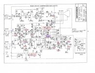
... I looked at schematics better and I've seen there are some point of measurement I could check with my multimeter.

Values are more or less equal to the schematics ones, except for two voltages. One should be 412 volts, but I got just a 2 volts;
the other should be 194 and my multimeter went out of scale (I was working with the 600v scale), it returned error (a "1" on the left side of the display).

I marked all values I got on this attached schematics; the wrong one are marked with a magenta box. The blue text is what I read with the multimeter.

321448 - TP evidenziati.jpg

Can it help to understand what's going on?
 
Does anyone here know what these things are? Are they magnets or the coils?

I don't know anything about the CRT circuits, but if these are the vertical and horizontal yokes, then position is critical.

You will need help from someone here on how to recenter and bond the yokes in place.
-Dave

Conforming with this picture:
http://www.repairfaq.org/sam/mon1rear.gif
they should be Purity/Static convergence Magnet Rings. Could it be the problem? Shouldn't appear at least something while booting? Expecially while the garbage appears for a while?
 
Does anyone here know what these things are? Are they magnets or the coils?

I don't know anything about the CRT circuits, but if these are the vertical and horizontal yokes, then position is critical.

You will need help from someone here on how to recenter and bond the yokes in place.
-Dave
There's usually no need to move any of this stuff, but it's not quite as critical on a monochrome CRT as it would be on a colour one. The position of the yoke itself (vertical and horizontal coils are combined in one assembly) is not at all critical; once you get a display, merely rotate it until the display is horizontal and gently tighten the clamp. The two rings (with tabs?) are probably the centering adjustment, a little trickier to get right but not bad. If there are any magnets stuck on around the outside you should definitely leave those alone. But leave everything alone unless it's already been moved.
 
Conforming with this picture:
http://www.repairfaq.org/sam/mon1rear.gif
they should be Purity/Static convergence Magnet Rings. Could it be the problem? Shouldn't appear at least something while booting? Expecially while the garbage appears for a while?
That's a colour monitor, an entirely different kettle of fish. No, I can't imagine anything there causing a blank screen; off-centre, tilted, a little out of focus perhaps, but you'll almost certainly see something.

Sounds like a problem in the horizontal drive/high voltage section. My current girlfriend is waiting for me and although she's not quite as, umm, excitable as my Brazilian one was I'm nevertheless not eager to incur her wrath, so this'll have to wait until I get back in a day or so; maybe you'll have solved it by then.

Good luck!
 
There's usually no need to move any of this stuff, but it's not quite as critical on a monochrome CRT as it would be on a colour one. The position of the yoke itself (vertical and horizontal coils are combined in one assembly) is not at all critical; once you get a display, merely rotate it until the display is horizontal and gently tighten the clamp. The two rings (with tabs?) are probably the centering adjustment, a little trickier to get right but not bad. If there are any magnets stuck on around the outside you should definitely leave those alone. But leave everything alone unless it's already been moved.

There are two brown rings with labels on the external side of the neck that are moving free (I didn't touch them, I simply discovered they are moving alone while I was moving up the monitor. And there is a white ring with a couple of magnets on it, in the inner part of the neck, that's blocked and I will never touch it :)

Now, about those measurements I did.... ...tell me, doctor, is it a serious desease? ;-)
 
Back
Top