• Please review our updated Terms and Rules here

AT to XT Keyboard Converter

How eerily appropriate... my 100th and 200th post have both been in this thread... I was busy on here the past month lmao!

Thought I'd give an update... I sent my Gerber files to a small scale PCB manufacturer, and got them back about 2 weeks ago. Before I placed an order, I made sure to correct a set of holes which were too small for the through-hole component (DIN5 connector)... turns out I STILL sent the old set of Gerber files with the too-small holes to the manufacturer anyway... great...

So before I release my Gerber files and final source code (just clean up the source tree), I need to drill some holes and make them bigger, as well as jumper a trace I may break through during drilling. I also need to make sure the Gerber files are CORRECT this time! I think I'll also add a PS/2 connector.

I'd like to take this time to explain... although this is a fun project, and I'm putting up my code/Gerber files for those who are interested, I will readily admit that Chuck's implementation is superior. Because he used a 5-volt tolerant PIC, and I only used a 3.3-volt compatible MSP430, his implementation needs fewer external components... and as I've found out, surface-mount capacitors are surprisingly expensive o.0;. The only advantage that I can think of mine offhand is that getting a cheap programmer (Launchpad- cost $4.30 plus time to set up software) to DIY is trivial.

Like Chuck's AT2XT implementation I believe, you need to connect the converter to a male-to-male DIN5 cable and connect the end of the cable to the PC.
 
Thanks--it should be observed that my prototype was constructed in one of the IBM "Monitor Miser" boxes that turn off your monitor after a period of inactivity until you hit a key. Tossed out the original PCB and kept the make coiled cord and used the same hole for the female connector that the original had. Looks nice. If I had to do it again, I'd probably select a different MCU.
 
Well, my implementation is out of commission for a while... All three of my PCBs are a loss due to me thinking I had good soldering skills, and the prototype has failed too. I probably shouldn't have used surface mount components, but on the slim chance I sold some of these, it would've been worth the trouble. TSSOP is not human-friendly soldering. No doubt that the advent of surface mount ICs, the desire for mass production and only making it practical for computers and machines to build PCBs and place ICs have killed off hobbyist electronics.

At least the prototype is fixable, but I think I'm done with the soldering iron for a bit.

... F*** surface mount. Seriously. It epitomizes everything wrong with electronics in the quest to make money.
 
Ok so I built a perfboard version of this and I am getting a 301 error on my XT. What programmer was used to program the PIC? I have an EPROM programmer that supports the 12f629 but when I erase the PIC something about OSCAL near the bottom of the dialog box and it's at 0xF. How dows one set the OSCAL to 0x3ff? Also what program was used to compile the code?

Also if using a standard US keyboard is the jumper plug needed or can I short pin 4 to ground?
 
You should be able to leave the jumper off if it's a US keyboard.

One caution is that when Andrew drew the schematic, I think the DIN pin numbering got hosed. Let me check my original prototype and I'll check it for you.
 
but when I erase the PIC something about OSCAL near the bottom of the dialog box and it's at 0xF. How dows one set the OSCAL to 0x3ff?
Buy a batch of ten PIC12F629, and you will probably find that each has a unique OSCCAL calibration word.

A description of the OSCCAL calibration word is [here].

There is more information in the latter pages of the document [here].
 
You should be able to leave the jumper off if it's a US keyboard.

One caution is that when Andrew drew the schematic, I think the DIN pin numbering got hosed. Let me check my original prototype and I'll check it for you.

Hi
The strange pin out connection of the DIN has to do with the default part footprint in KiCAD. I merely used what is there already and made adaptations. I verified it came out correctly in the physical part foot print on the PCB. I do not recall anyone indicating the connections were wrong on the PCBs we produced. The AT2XTKBD PCBs worked well as I recall.

Thanks and have a nice day!

Andrew Lynch
 
The strange pin out connection of the DIN has to do with the default part footprint in KiCAD. I merely used what is there already and made adaptations.
The diagram that you are referring to is the "Schematic view #2" link on the AT2XTKB wiki page. That link is annoted "(arrangement of pins on large DIN connectors is wrong)" to alert people to the DIN pin arrangement issue.

The diagram displayed via the "Schematic view #1" link reflects the correct physical layout of pins in the DIN connectors.

I verified it came out correctly in the physical part foot print on the PCB. I do not recall anyone indicating the connections were wrong on the PCBs we produced. The AT2XTKBD PCBs worked well as I recall.
I can vouch for that. I assembled at least 10 units.
 
Ok FYI I wired it according to schemtic 1 so I know it is wired correctly. What I need is the OSCCAL value. But if each one is unique how do I find it?
 
Last edited:
What I need is the OSCCAL value. But if each one is unique how do I find it?
It is set at the factory. If the value in the chip gets overwritten, then some kind of external frequency reference (e.g. signal generator) is required to determine the OSCCAL value for a particular PIC12F629. The information is on the Internet.

In the early days, I did not know what an OSCCAL value was, and I was in ignorance overwriting it. I am positive that it did not affect operation of the AT2XTKB converter (i.e. suggesting that the AT2XTKB code that Chuck wrote does not require the 4 MHz clock to be accurate).
 
Well, my implementation is out of commission for a while... All three of my PCBs are a loss due to me thinking I had good soldering skills, and the prototype has failed too. I probably shouldn't have used surface mount components, but on the slim chance I sold some of these, it would've been worth the trouble. TSSOP is not human-friendly soldering. No doubt that the advent of surface mount ICs, the desire for mass production and only making it practical for computers and machines to build PCBs and place ICs have killed off hobbyist electronics.

At least the prototype is fixable, but I think I'm done with the soldering iron for a bit.

... F*** surface mount. Seriously. It epitomizes everything wrong with electronics in the quest to make money.

Hi
Well I can appreciate the sentiment but it may be a bit overstated. SMT PCB can be done on a hobbyist level but is more difficult. Not at SMT devices are the same either. There are some with larger pitch which are easier than those with fine or very fine pitch leads. TSSOP packages I would consider fine pitch.

What sort of soldering set up are you using? One thing that will help a lot is a generous application of liquid flux on the circuit in solder pads in question. That will help "wet" the pads and leads and generally help the solder flow more easily.

That being said, generally speaking I find SMT to be a PITA and requires good lighting and direct magnification and a good soldering iron set up. I have found PTH/DIP technology lets you get away with a lot so it is inherently more hobbyist friendly.

Would you please post some photos of your PCB, setup etc. Maybe there are some tips people can offer to help.

Thanks and have a nice day!

Andrew Lynch
 
In fact, given my druthers, I'd probably use an ATUSB AVR, as I mentioned before. Not for the USB support, but rather for the PS/2 keyboard support on the USB pins--and that the same pins can be used to program the thing, as it comes pre-programmed with its own bootloader. But it's SMT and that puts a lot of people off--an 8-pin DIP, on the other hand is doable on perfboard.

And yes, the "slop" in frequency is pretty wide for this application.
 
Okay, on the OSCCAL clobbering, which seems not be be unknown in the lower PIC world. First off location 3FF must contain a RETLW ((34xx) instruction. XX is the calibration value, but it's a compound value. I'd start out with a middle-of-the road value if I were guessing, such as 348C might be a nice middle-of-the-road value.

If you're serious about this, here's a cool rig that uses line frequency to set the calibration value:

http://picprojects.org.uk/projects/recal/recal.htm#Code,_schematics,_construction_

Note that OSCCAL is just a program memory location--it has no direct tie-in to any hardware function. If you look at the initialization code in my routine, you'll note that 0x3FF is called, then the resulting value is written to the OSCCAL register (90h in the second bank)--and that's what does the trick. If you wanted, you could just comment out that code in the source and let the 629 take factory pot-luck.
 
So what's next? Someone want to do a USB-to-XT converter?

After looking around for a while, I arrived at the PIC32MX203 as a low cost (and available in non SMT, if folks care) option that has USB host mode. It's taken me a few weeks to get a dev environment up and running (I had an unused PICkit2, but it initially did not work, so I ordered a PICKit3, only to have it only work in the GUI, and I refuse to tie projects to use of a GUI, so I found pic32prog.exe which works with the PICKit 2, and now I have a working dev board).

Now, I just need to find a host-mode lib for USB for the unit (LUFA is nice, but it's for AVR, so looking for something for the PIC32).

Jim
 
I use the big PIC32xx SMT devices (795, etc.). Although it may not affect your applications, be sure to obtain and read the errata sheets before you make a serious investment. At least on the 795s, I discovered that there were a couple of "you can't get there from here" errata that essentially torpedoed a project. Fortunately, there were several ARM variants that could do the job.

Somewhere I have a JTAG programmer project bookmark set for the PIC32. (The PICKit-style programming uses the on-chip converter to go from ISP to EJTAG; some have discovered that it's much more robust if one simply starts with JTAG).

It's a good idea to glue a small faucet washer around the "reset" button on the PICKit. That button is totally incompatible with PIC32 operation and nasty things have happened that render a PIC32 un-programmable if the button is inadvertently pushed at the wrong time. Also, be aware that if programming is somewhat erratic, the best approach is to raise the supply voltage a bit. I've got some PIC32s that won't program at 3.3V, but do just fine at 3.5V.
 
Last edited:
Okay, on the OSCCAL clobbering, which seems not be be unknown in the lower PIC world. First off location 3FF must contain a RETLW ((34xx) instruction. XX is the calibration value, but it's a compound value. I'd start out with a middle-of-the road value if I were guessing, such as 348C might be a nice middle-of-the-road value. .

Ok i'll give that a shot.
 
Thanks, Chuck!

Thanks, Chuck!

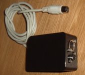
Just a quick note to say thanks for the information in this thread. I've built up a unit using the code provided by Chuck in post #280 (the later version didn't have a hex file). I didn't have any problems with OSCCAL, I programmed it using a minipro programmer, just loaded the hex file and hit program.
XT to AT converter.jpg
I'm now able to get started fixing up a 5160, it's been sitting there with a 301 error waiting for F1 to be pressed since I got it.
There is a full article on my blog here:
http://blog.tynemouthsoftware.co.uk/2013/10/keyboard-error-press-f1-ibm-5160-part-3.html
and the previous articles:
http://blog.tynemouthsoftware.co.uk/2013/09/vintage-ibm-5160-xt-teardown-part-1.html
http://blog.tynemouthsoftware.co.uk/2013/09/vintage-ibm-5160-xt-teardown-part-2.html

There are mentions within this thread of an IDE or CF card interface for XT's, is anyone still making / selling those?

Thanks,

Dave Curran
 
Last edited:
Back
Top