• Please review our updated Terms and Rules here

8250 faulty drive

The address lines are confusing, but let's start with the D4 data line. It is stuck low while the others are pulsing. Check all the many places D4 connects for solder splashes or shorting.

Dave, sorry for that, but either I don't understand or I'm missing something. You told the D4 line, but afaik it's the eprom pin 16, and it's pulsing (all the data lines are pulsing).

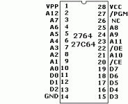
As quick reference:

27C64-eprom.gif


--Giovi

---------------------------------------------------------------------------------------------------------------------------------
p.s. [OT] - I'm in trouble with the damn'd pet too, so if you would to take a look to my other thread, it would make my day better ;-)
p.p.s. yes, I know, I'm a pest :D
 
Last edited:
I did a visual check, redone some suspect solder joints, washed the board... nothing. Still two flashes. :-(
As told, I did the inverter with a spare chip.
Mike, does the 2764 adapter + inverter work fine on your 8250 (if you have time/chance to test one on your drive) ?
 
ok, thank you, no hurry at all, I can live for a while without a 2 x 5.25" disk drive ;-)
I'm probably not qualified...

I've used, modified and designed/built/sold various RAM/ROM adapters for PCs, PETs, AIM65s and even Tandy M100s over the years, including one for an AIM65 that puts all 3 1/2 of its languages into one EPROM.

This weekend I decided to make a neater version; aside from the standard 2532>27256 connections it only has two added diodes, a resistor and one jumper, and yet I've spent the better part of the weekend on and off triple- and quadruple-checking all the connections and have still not found why it doesn't work. Old age is definitely taking its toll...

Anyway, the Micropolis 8250 board that I happened to have beside me seems to work, so I should be able to test whether what we're talking about actually works.

Jim Brain makes a '23xx' adapter with selectable chip select polarity suitable for the CBM disk drives, but unfortunately I only have the older '2364' version:
http://store.go4retro.com/adapters-1/
 
Old age is definitely taking its toll...

I think you only need some beers and a couple of caipirinhas; it should work .... at least it always works for me ;-)


Anyway, the Micropolis 8250 board that I happened to have beside me seems to work, so I should be able to test whether what we're talking about actually works.

Jim Brain makes a '23xx' adapter with selectable chip select polarity suitable for the CBM disk drives, but unfortunately I only have the older '2364' version:
http://store.go4retro.com/adapters-1/

I'm trying to understand if the problem is the ROM/EPROM, or it is not. Neither the original rom nor the eprom adapter are working and I'm starting to believe that maybe another faulty chip, bad socket, etc. is responsible for the issue.

As told somebody in the past socketed all the chips and, though it seems to be a well done work, I can't say if he introduced some other errors.

I didn't spend much time on this drive yet, since I was also fixing the PET. But I will take the schematics and I will take a look to the signals with the scope and maybe I will try to replace at least the most concerned chips.
 
I think you only need some beers and a couple of caipirinhas; it should work .... at least it always works for me ;-)
I used to have a Brazilian girlfriend but unfortunately (for me, fortunately for her I'm sure ;-) ) she decided to marry someone else; maybe I should ask her for a good recipe... :winkingdevil:
I'm trying to understand if the problem is the ROM/EPROM, or it is not. Neither the original rom nor the eprom adapter are working and I'm starting to believe that maybe another faulty chip, bad socket, etc. is responsible for the issue.
With your luck, almost a certainty ;-)
 
I used to have a Brazilian girlfriend but unfortunately (for me, fortunately for her I'm sure ;-) ) she decided to marry someone else; maybe I should ask her for a good recipe... :winkingdevil:

In a big glass cut about 2/3 of a lime (http://bananeirasagora.com.br/images/noticias/7587/limao_galego_g.jpg) in small pieces, add sugar (3 tea spoons) and press all together; then fill the glass with ice cubes and then fill the empty space with cachaça. :D

With your luck, almost a certainty ;-)

remove "almost" ;-)
 
In a big glass cut about 2/3 of a lime (http://bananeirasagora.com.br/images/noticias/7587/limao_galego_g.jpg) in small pieces, add sugar (3 tea spoons) and press all together; then fill the glass with ice cubes and then fill the empty space with cachaça. :D
Thanks for that, but I'm still inclined to call her just to annoy her husband ;-)

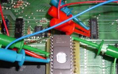
OK; I tried the modified 2764 and it does work:
8250ROM.JPG
This adapter is the same as yours except that pin 20 (/CE) is connected to pin 22 (/OE), so I also pulled pin 20 and connected it to pin 14 (GND), the green wire.

The red wires connect UL1 socket pin 22 (CE) to UJ2 pins 12 and 13, and the blue wire connects the inverted /CE from UJ2 pin 11 back to the lifted UL1 pin 22.

Can your programmer read a 68764/64766? If so, you should be able to read the 2764 in the adapter (with pin 22 connected normally of course) just to verify that the adapter is OK.

An interesting note, since you seem to be blinking once or twice: with UL1 completely removed the LEDs blink three times. Since you blink twice with a non-inverted CE which is the same as no UL1 at all, that would suggest that there is indeed another problem(s) somewhere.
 
Thanks for that, but I'm still inclined to call her just to annoy her husband ;-)

AH AH AH AH AH AH YOU'RE A BAD, BAD BOY!!! ;-) [[Never give up! :D ]]

OK; I tried the modified 2764 and it does work: View attachment 15908 This adapter is the same as yours except that pin 20 (/CE) is connected to pin 22 (/OE), so I also pulled pin 20 and connected it to pin 14 (GND), the green wire. The red wires connect UL1 socket pin 22 (CE) to UJ2 pins 12 and 13, and the blue wire connects the inverted /CE from UJ2 pin 11 back to the lifted UL1 pin 22.

Thank you for your test and your time. If I'm right, you are now I my same condition, aren't you? I only used a spare inverter.

Can your programmer read a 68764/64766? If so, you should be able to read the 2764 in the adapter (with pin 22 connected normally of course) just to verify that the adapter is OK.

No, unfortunately it can't.

An interesting note, since you seem to be blinking once or twice: with UL1 completely removed the LEDs blink three times. Since you blink twice with a non-inverted CE which is the same as no UL1 at all, that would suggest that there is indeed another problem(s) somewhere.

I can extract the whole ROM or EPROM and it still blinks twice. I still had no time to look at schematics and investigate about what can be involved with UL1 (of course admitting I can understand something about schematics, that's quite improbable ;-) ) I won't be so amazed if I will discover the original ceramic ROM still works and the problem is elsewhere.

Have you any clue about what I should check in first? Maybe an investigation on signals on the ROM pins could help...?

--Giovi
 
You've got a late PET and/or a 40/8032 with spare ROM sockets, right? Maybe you could try reading the 8250 ROMs (and testing your adapter) in one of them; it would of course still require inverting pin20 and you'd only read the upper half unless/until you lift and ground pin 21.

Just hope it's not the 6530; they're unobtainium although I believe some workaround kludges do exist.
 
You've got a late PET and/or a 40/8032 with spare ROM sockets, right? Maybe you could try reading the 8250 ROMs (and testing your adapter) in one of them; it would of course still require inverting pin20 and you'd only read the upper half unless/until you lift and ground pin 21.

Let me see if I understood correctly. I can put a 64k eprom into a 2332 socket and I can read it by the 8032; I only need to invert the ROM pin 20 through (i.e.) a free port of a 7404 and, if I lift and ground the ROM pin 21, I can read the lower part. Is it correct, and is it all?
I suppose I will access the monitor using sys 1024, but can you tell me the command for read it? I used that command in the past but I can't remember how I did....


Just hope it's not the 6530; they're unobtainium although I believe some workaround kludges do exist.

Yes, Ruud Baltissen recently told on the cbm-hackers mailing list he succeded making a 6530 out of a 6532 ( http://www.baltissen.org/newhtm/6530repl.htm ) but it's quite tricky for me, so I also hope it's not the 6530. And I only have a 6530 replacement for a 8050 :-/

At the moment I have no clue the 6530 isn't working (no error code for broken 6530) and of course I hope I will never see it!
 
Let me see if I understood correctly. I can put a 64k eprom into a 2332 socket and I can read it by the 8032; I only need to invert the ROM pin 20 through (i.e.) a free port of a 7404 and, if I lift and ground the ROM pin 21, I can read the lower part. Is it correct, and is it all?
I suppose I will access the monitor using sys 1024, but can you tell me the command for read it? I used that command in the past but I can't remember how I did....

The 2332 and 2764 both have negative going chip enables so no inverter is necessary. As far as reading the ROM, it seems to me we created a short BASIC program that will perform a sum check somewhere on the forum. I'll try to find it.
 
Anders and MikeS optimized my first cut at a modulo 256 sumcheck program of a 4K EPROM in the $9000 socket of a PET.
10 for i= 9*4096 to i + 4095
20 s = s + peek (i)
30 next i
40 print " Sumcheck = " s - int(s/256) * 256
 
The 2332 and 2764 both have negative going chip enables so no inverter is necessary. As far as reading the ROM, it seems to me we created a short BASIC program that will perform a sum check somewhere on the forum. I'll try to find it.
Did I miss something again? I think on the 8032 we have the opposite situation from the 8250; we don't need to invert CS for the adapter but we do need to invert for the original 8250 ROMs, no?

@Giobi:
Try this:
- Insert your adapter with the 2764 into the 8032's A socket (UD11) with all pins connected.
- Turn on the 8032 and type:
S=0:FOR X = 10*4096 to X+4095:S=S+PEEK(X):NEXT: ? S

After a few seconds it should give you a total of 485835.

If you like, lift pin 21 of the adapter or pin 23 of the 2764, connect it to GND (pin 12 or 14) and run the above again.
This time you should get 477492.

If that all checks out, do the same with your ROMs, inverting pin 20; 901887-01 should be the same, and 901888-01 ROM should give 514792 and 468967 respectively.

Edit: Looks like Dave beat me to it while I was typing.
I never saw the point of the modulo 256 when you're doing it in BASIC; convince me, Dave! ;-)
 
Last edited:
Anders and MikeS optimized my first cut at a modulo 256 sumcheck program of a 4K EPROM in the $9000 socket of a PET.
10 for i= 9*4096 to i + 4095
20 s = s + peek (i)
30 next i
40 print " Sumcheck = " s - int(s/256) * 256

How about this?
Code:
40 print " Sumcheck = " s and 255

Would this work? :D
 
Did I miss something again? I think on the 8032 we have the opposite situation from the 8250; we don't need to invert CS for the adapter but we do need to invert for the original 8250 ROMs, no?
You are quite right. For some odd reason I was thinking Giovi was to test a 2764 in the PET.

I never saw the point of the modulo 256 when you're doing it in BASIC; convince me, Dave! ;-)

Yes, a total sum is easier in BASIC. But remember the table of sum checks for all PET ROMs you posted on the forum is in modulo 256. This will be extra useful when the petester diagnostic EPROM performs check sums as well as RAM checks in assembly language. Now you have to add these PET Drive ROMs to your table. So you recalculate those numbers! :)
 
Yes, a total sum is easier in BASIC. But remember the table of sum checks for all PET ROMs you posted on the forum is in modulo 256. This will be extra useful when the petester diagnostic EPROM performs check sums as well as RAM checks in assembly language. Now you have to add these PET Drive ROMs to your table. So you recalculate those numbers! :)
Damn! I just looked and you're right; I made both versions but at a fast look only saw the table of totals on my computer. Sigh...

@ giobbi: while you're at it you might as well check the 6316 UK6:
- Lift pin 21 and connect to GND (pin 12); insert in A socket as before.
FOR X=40960 to X+2047:S=S+PEEK(X):NEXT: ? S
You should get 157792
 
Last edited:
Back
Top