• Please review our updated Terms and Rules here

Looking for the file ZRQCF0 (xxdp25 or 22)

MauriceH

Experienced Member
Joined
Apr 2, 2014
Messages
399
Location
Dordrecht , Netherlands
I can not find this file ZRQCF0 in any of the on line FTP sites.
XXDP25, XXDP22,several other files containing xxdp etc.

Those only have the ZRQFC0 file and that does not test the RD31 (st225)
Only RD51-52-53-54

The ZRQCF0 does include the RD31 attached at the RQDX3 card.

ZRQCF0 is mentioned in the
PDP11_DiagnosticHandbook_1988.pdf

2e
Also Format with ZRQCH0 I assume also does not Format the RD31 (st225)
After an error report it is set to type RD51, so Think CH0 does also not have
the 31.

Does anybody know what file XXDP ZRQ??? does format the RD31 on RQDX3 card?

Thanks
Maurice
 
ZRQCH0 was the last release of the RQDX formatters. It supports ALL RD formats.

How are you connected to the controller? With a real DEC distribution board?

Don't forget that the drive needs to be set to DS3, if it is not already set,
and the drive DOES need to have it's terminator installed.

The typical DEC panels have READY and WRITE PROTECT switches on them.
The controller expects to see the READY signal; not sure how it would react
if either of the signal lines were left floating.

If your drive has been formatted in another system (i.e., a PC with an MFM controller)
then you cannot use the automatic formatting settings, you have to pick the specific drive manually.
The RD31 is clearly listed in the menu of ZRQCH0.

(My system is still in moth balls, or I'd walk you through it.)
 
Thanks,

I don't have the org BA23.
I made a board exactly same according this site
http://www.cosam.org/computers/dec/pdp11-23/20080409.html
I'll go check the Ready signals.
I have seen the layout of the BA23 when search the internet and notised the several switches.
Came accros the self made version and build that one.
Have the ID set 3 and the terminator.
Maybe indeed manualy set a switch point to that signal, I go probe with a scope.

With your repay I now understand the difference in automatic Format.
I''l check again the manual settings and how to choose the RD31.

Maurice
 
It's been years since I've worked with MFM drives
on the PDP-11, so most of the following is mostly recollection -

ZRQCH0 queries the disk, to try to determine what type of drive it is.

I *think* that it looks for a table stored on the drive that may only be present
on drives that have already been formatted on an RQDX controller.

If it can't figure out what it is, it assumes that it is an RD51,
and attempts to format the drive as an RD51.

Here is a section of the dialog from the program -


MSCP Controller Model: 19
Microcode Version: 4

Do you want to use manufacturing bad block information [Y/N] (A) N ?
Downline load UIT [Y/N] (A) Y ?

UIT Drive Name
-------------------------------------------------------
0 RD51
1 RD52 part # 30-21721-02 (1 light on front panel)
2 RD52 part # 30-23227-02 (2 lights on front panel)
3 RD53
4 RD31
5 RD54
6 RD32

Enter Unit Identifier Table (UIT) [0-7] (D) ? 5
Continue if bad block information is inaccessible [Y/N] (A) N ? Y
Please type in the serial number [8-10 digits] (A) ? 05388342

Formatting of Drive 1 Begin.


Hopefully this helps. . . .
 
Booting from TU58 EM XXDP V2.5
ZRQCH0.BIN
Running in Small Monitor:

After the Autoformat? N <CR>
There is an error:

ILL INTER 100
PC 047734 PS 000200

ILL INTER 100
PC 051016 PS 000200
DR>
 
Let's verify the RQDX3 jumper settings -

Address jumpers at default -

Starting at jumper W1 -

01011000101 (i.e., jumper W1 removed, jumper 2 installed, jumper 3 removed, etc.)

This should put it at 17772150

Jumpers W12 through W17 should all be REMOVED.

Jumper W23 - Pins 1 & 2 connected. (Furthest from the drive connector)


Your primary MXV11 (with the console port) -

J30 to J31, J32, and J33 (Ram Bank 0)

J13 to J27 (SLU's to 176500 and 177560)
J14 to J25
J15 to J26
J18 To J23
J19 to J24 and J28

J51 to J56 (Vectors to 300, and 60)
J52 to J54 to J55
J53 to J57

If you feel the need to use the other MXV11 during this process,
then verify that the following SLU jumpers on your second MXV11 are set -

J12 to J24 (SLU's to 176510, and 176520)
J13 to J27
J16 to J26
J17 to J25
J18 to J23
J19 to J28

J51 to J54 (Vectors to 310 and 320)
J52 to J53
J55 to J57
J56 to J58

Bring the system down to it's minimum configuration -

------M8186------ ------- MXV11 -------
------Empty------ ------- M7555 -------

XXDP+ should be OK in 32K of memory.

Then try your boot, and format again.

Another thing that you COULD try, is to
move the RQDX controller next to the CPU.
Although this configuration isn't recommended, it should still work.

If it suddenly starts working by having the card next to the CPU,
then chances are that there is something wrong with the MXV11,
and it's not passing interrupts.


Tim
 
Ok getting warm.

Jumpers MXV11 checked-are ok.
Jumpers M7555 checked-are ok - only 2 are not mentioned also not in the manual.
Those 2 are located at : left side , left near the last prom of 4, both are in.
-connector HD to the belly, richt side are the jumpers,

First:
------M8186------ ------- MXV11 -------
------Empty------ ------- M7555 -------
* System trying to boot (at the PC TU58em with options -V -D I notised running char..)
ERROR
@000104 containing code 000106 (after 000104/000106)

System is halt,
The LED Stay's ON at the M7555! .(initialasion I Thought, should be going OFF after seconds)

2e try
------M8186------ ------- M7555 -------
------Empty------ ------- MXV11 -------
* System trying to boot (at the PC TU58em with options -V -D I notised running char..)
ERROR
@000104 containing code 000106 (after 000104/000106)

System is halt,
The LED Stay's ON at the M7555.

3e try
------M8186------ ------- MXV11 -------
------M7555------ ------- MXV11 -------

M7555 Led goes OFF after Init
System boots normaly.

Booting from TU58 EM XXDP V2.5
ZRQCH0.BIN
Running in Small Monitor:

After the Autoformat? N <CR>
There is an error:

ILL INTER 100
PC 047734 PS 000200

ILL INTER 100
PC 051016 PS 000200
DR>

I notised before with the config
------M8186------ ------- MXV11 -------
------M8059------ ------- MXV11 -------
------M8029------ -------M7555---------
That also the LED on The card stayed ON.
ALso the card M8059 is not working as XXDP keeps running in SM.
Changed places M8029 and M7555 the LED goes off as it should be.

The config I was working with was
------M8186------ ------- MXV11 -------
------M8029------ ------- MXV11 -------
------M7555------ -----------------------

So what is going wrong at the right side of the base?
@000104/000106
Checked the connectors visially but seems ok, no bend connectors
to be found.
Changed the M8186 (as I now have one with Floatingpoint)..
same problem.
 
Made for the finish a test with RX02
The config
------M8186------ ------- MXV11 -------
------M7555------ ------- M8029 -------
-------------------- -----------------------

A normal boot with Floppy RX02.
Also a DIR DY0: works fine.

Boot this config from TU58em with XXDP
LED M7555 goes Off.
Again failure @000104/000106

The config
------M8186------ ------- MXV11 -------
------M7555------ ------- MXV11 -------
------M8029------ -----------------------
Normal Boot XXDP (but had to made several times reset
befor the @104 dissapears and system boots)

ZRQCH0 again
Ill Inter 100
etc.
Notice that M8029 and M7555 is switched accoring previous setting
that i was normaly working with.
 
You mentioned that you have an H9270 backplane, and that it is 22-bit.

Are you absolutely certain it is the 22-bit variety?

There are at least two types of H9270 backplanes.

The base H9270 model, as originally distributed in LSI-11/03 systems was a 16-bit backplane.

This can be seen on pages 3-4, and 3-5 of the LSI-11 PDP-11/03 manual.
Pins AC1, AD1, and BC1 - BH1 are tagged as "spare" lines which are NOT bussed.

Further, on page 3-7, you can see that the address lines stop at BDAL15L,
which indicates that it is only a 16-bit backplane.

A later model, the H9270-Q was apparently a 22-bit backplane.

If you have one of the older models, that could be a potential source of your problems.

Check out Micronote #005 -

Processors, memories, or DMA devices which are not capable of 22-bit
addressing may generate or decode erroneous addresses if they are used
in systems which implement 22-bit addressing. Memory and
memory-addressing devices which implement only 16 or 18-bit addressing
may be used in a 22-bit backplane, but the size of the system memory
must be restricted to the address range of those devices (64 KB for
systems with 16-bit devices and 256 KB for systems with an 18-bit
devices).


NOTE
Eighteen or sixteen bit DMA devices can potentially work in
Q22 systems by buffering I/O in the 18- or 16-bit address
space.

So. . . . if you're on a 16-bit backplane, that could explain why your memory isn't showing up properly.

If you haven't done so already, make a visual inspection of your backplane,
and/or check it out with a volt-meter.

A 22 bit backplane will have pins AC1, AD1, and BC1 through BF1 bussed.

If not, you will have to modify the backplane to buss the signals to the other slots.
 
Last edited:
Thanks for the effort to help me debug the problem.

I put some pictures of my pdp1123 on my site
with a close-up of the H9270 label.
http://84.86.9.180/Computer/PDP1123/pictures_pdp1123.htm

To be seen a redating to 12-5-80, so must be some changes made back then
by former owner.(I own it sinds 1992)
Then at ETCH there is a new "E" code written.
Could that E mean it was changed from 03 to 23?

I will look into the matter of your suggestions at the base pinout, if
it is a 22Bit backplane.
Otherwise I have to change it.
That is just some strapping?
Or more to be done?

Maurice
 
I corrected my earlier post -- the RQDX3 does support DMA operations on 16 and 18-bit busses.

A 16-bit bus, however, will allow you a maximum of 64K memory
(32K Words, with 4K being taken up by the I/O page, for a total of 28K Words)

An 18-bit bus will let you go up to 256K, and 22-bit to 4096K. . .

Making the modification is easy, if you have a wire-wrapping tool.

1.) Pull the backplane.

2.) Determine the correct pins on slot #1 of the backplane.

3.) Wire-wrap from slot 1 down to slot 2. . . then down to slot 3. . . and then slot 4.

4.) Since this is a Q/Q backplane, then you'd need to do the same on both sides of the backplane,
and then link the two sides together.


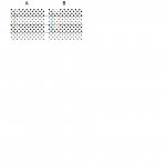
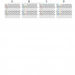
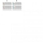
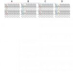
I've attached some diagrams to give you an idea what to look for.
Although you have a Q/Q backplane, which has slots AB on the left and right sides,
I labeled the diagram in Q/CD format -- i.e., slots A, B, C, and D.
This should make my explanations a little more clear.
Color-coded pins should be bussed together.
For example, the diagram shows how pins AC1 and CC1 (in RED) should be bussed together.
It also shows how pins BC1 and DC1 (in BLUE) should be bussed together.
The remaining color-coded pins should be bussed together the same way.

This should be enough to give you an idea of what you need to do.


A good plan of attack would be to first CHECK to see if the various lines are bussed.
Use the color-coded diagram, to make sure that pins of the same color are all bussed together.
Red, and Green are the pins required for 18-bit addressing.
Blue, Brown, Yellow, and Purple are the 22-bit addressing lines.

If you're not sure, you can always post a photo of the backplane.

Backplane_3.jpg

Backplane_4.jpg
 

Attachments

  • Backplane.jpg
    Backplane.jpg
    5.3 KB · Views: 1
  • Backplane_2.jpg
    Backplane_2.jpg
    8.6 KB · Views: 1
My H9270 is already traped as a 18Bit.
Red-Green in your drawings.
Did a quick check some other pinning to see if there is
something of disconnection to "C/D" ast to say.

I'll go find my wrap tool and wrap it to 22Bit.

Put also Pics from the M7555 on my site.
Saw there are several versions on the net.

The 2 Jumpers near the fourth prom .between the 2 cristals
I see several on the net also installed.
 
Hmmm. Well, with the backplane already at 18-bit,
that kind of rules out the 64K memory theory.

The RQDX3 is strapped correctly.

Just out of curiosity, does it make any difference
if you swap the positions of the MXV11 boards?

Also -- before you add the 22-bit addressing,
check your M8186 to make sure it is rev "C" or later.
The rev will be stamped in the purple plastic handle,
on the solder-side of the board.

(Usually, you'll see a letter, followed by 2 numbers, such as D 23)

Rev "A" or "B" boards aren't 22-bit compatible.


Quick question -- Are you using a separate power supply with the disk drive?
The 11/03 power supply isn't very powerful, and shouldn't be used for anything
other than the cards in the cage.
 
Last edited:
Also -- before you add the 22-bit addressing,
check your M8186 to make sure it is rev "C" or later.

-Its a "050 C3" version.
KDF11 CPU 5013326C M8186
(Used to had a Floating point, a I first time noticed now, there is 1 last broken
pin in 1 socked to be found)
Time stamps on the parts are all app 1980 (W05 till 35)
exept the CPU that is only one dated 1984/W32.

2nd CPU card with Floating Point (just bought) "252H D0"
KDF 11 CPU 5013326 D-P4
Most parts dated app 1982
MMU - 1982
Floating point 1980
CPU 1980

Quick question -- Are you using a separate power supply with the disk drive?
-quick answer...NO....
Could that be the problem....
Powersupply is a H786 as I think (at least No H780 that one has a transformer.)
Tomorrow I'll try with a separate CPU Powersupply to drive the HD.

And leave for now the strapping to 18 BIT.
I'll be back
 
As long as your CPU is rev "C" or higher, it will be fine for 22-bit.

The MXV11's won't care about the extra lines,
and will work just fine if you keep them as the first two banks of memory.
 
Have you by chance run a diagnostic on the MXV11 cards ?

I think the file you are looking for is VMXAAO or similar.
(As long as it contains VMXA at the beginning.)
 
Used an external PSU for powering the ST225 HD.
No luck.

WireWraped To 22Bit
Config just CPU, 2x MXV11's and the RQDX3.
No Luck.

The error's
Ill Inter 100
PC 047734 PS 000200

ILL Inter 100
PC 051016 PS 000200

Go find the VMXA... and test my cards as adviced.
I have I think its a 4 serial line card but can't find anything about it.
Maybe with the M8059 (128K) I could give it a try, but just putting in
instead of the two M8047's it does not give a char on screen.

A Model 304
GTSC Made in USA
JCi-Dis-T 94V
Copyright 1984

4x IM6402IPL are on board and the DataSheets tell they are Uni ASync RX/TX so
must be a 4 serial linecard I Think, but the strappings???

pics to be found here
http://84.86.9.180/Computer/PDP1123/pictures_pdp1123.htm
 
uhmm....
Run the VMXAA0.BIC... on the M8047.
Also with only M8186 and first M8047.
Default
SWR: 000000
Dec:000000

Posted the pictures on my site.
..
TEST #000004, ERROR# 34, PC=--3064
TEST #000012,ERROR# 71,PC=004450,CSR:176500,VECTOR:000300
TEST #000013,ERROR#73,PC=004552,CSR:176500,VECTOR:000300
TEST #000014,ERROR#16,PC=004650,CSR:176500,VECTOR:000300
TEST #000016,ERROR#111,PC=005366,CSR:176500,VECTOR:000300
TEST #000017,ERROR#124,PC=005562,CSR:176500,VECTOR:000300

Test #000024,ERROR#271,PC=010440,CSR:1777560,VECTOR:000060
TEST #00024
KEEPS LOOPING TEST #000024
With also bad characters
?p? ?4,ERROR#271,PC010440,CSR:177560,VECTOR:000060,CSR? ?0?ROR# 0
? 271,pc=010440,csr
TEST #000024,ERROR#271,PC=010440,CSR: 177560,VECTOR:000060
ECT.
 
Last edited:
VMXAA0 could be looking for a loopback connector to be installed on the serial ports,
which might explain the errors on test # 12 - test # 17.

Test #24 may be because the console SLU is obviously in use. Heheh.

Test #4 though. . . . not sure what that particular test refers to.

Although I've never seen the MXV diagnostic in use, I was hoping that
it would be a bit more informative about what it was doing.

(Specifically in testing the on-board memory. . .)

Are there any other similar tests available, such as ZMXAA0 ?
(Other than VMXAA0, I wasn't able to readily find references to
MXV11-A diagnostics. . .)
 
Back
Top