• Please review our updated Terms and Rules here

Full Page Display signal on a non-FPD monitor?

Unfortunately that lends support to my theory that it's something completely proprietary. :/

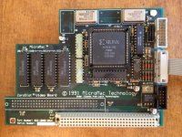
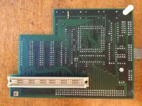
I looked at the thread you had posted on that other site to see if you'd posted a good high-res shot of the card; it looks like there's a photo of the component side; it's a long shot, but can you see enough traces on the reverse side to see if there are any common lines going to "JP1" and "JP2"? (According to your post there the cable you have connects to "JP2"... I could swear at some point I saw evidence that the VGA dongle attached to "JP1" instead. Unfortunately the fact that both of those connectors have the same number of pins sort of suggests they're not a direct map between their pin numbers and the pins on the connector pigtail but, I dunno, maybe it might help make some educated guesses about what where the sync lines are and/if the luminance signal is sourced from the same place for both connectors?)

I was wondering if one of those CGA/EGA/etc scaler boards might help with this if it did turn out to be digital, but I do wonder if the frequency might be too high.
 
I'll take some higher res pictures. I have two of the video cards. One has 2 ports (JP1, JP2), and one has 3 (JP1, JP2, JP3). I was looking closely at the one with the 3 ports yesterday, I seem to recall that the JP1 and JP2 were connected. I'll take some pictures when I get home from work.

There is a very similar Lapis video card that shipped with a cable with both 9 pin and regular 15 pin VGA connectors.
 
Also, I counted the pins incorrectly. 8 and 9 are on the other side from that angle. The pins 6 and 7 are shorted, with 8 and 9 separate. It looks to be wired just like CGA, but when I connected it to my adapter, it said No Signal.
 
The other concern I have is I seem to recall after looking up one of the ICs on the picture of the card you posted that said IC near the JP2 connector looked like it might be an ECL transciever chip. That raises the possibility that the full-page monitor output is neither TTL nor Analog, and therefore you won't be able to feed it directly into any modern monitor, and your scaler board isn't likely to like it either. (On the subject of your scaler board, have you checked/verified what its input pinout is? I ask because this outfit specifically says a 9-to-15 pin cable meant for hooking up a multisync monitor doesn't work on their input plug. I still suspect the output frequency from a FPD board is going to be too high for a "CGA scaler" to handle anyway.)

Attacking this from the other direction: Is there any documentation as to what brands/types of full page monitor went with this card? There were several vendors selling FPDs and they differed from each other in size, resolution, and quite possibly interface. If you could track down someone who has a compatible monitor but is using it with a different card (best case: has it hooked up to a conventional Mac 15 pin port?) maybe it could be useful to get the pinout of the cable?

I honestly have no idea why you'd short pins 6 and 7 if it were a "CGA" pinout; pin 6 is "intensity" and 7 isn't supposed to be connected. On EGA that would be tying two secondary color bits together, which again doesn't seem very useful. I'm curious about what the source of the "ECL" pinout on this page is, I didn't know there was ever a standard for that... but as it is it uses 6 and 7 for Video and Return so you'd likewise not accomplish much tying those together... So, what's left there is "MDA"; the *potentially* interesting thing there is 7 and 6 are video and intensity respectively on MDA. With TTL video "intensity" is essentially the grayscale bit; your 4 grayscales are "Bright White"; "White (light grey)"; "Bright black" (dark grey); and "Black". If you were using a TTL monitor like MDA as a one bit monitor, as you would in this case... maybe you'd tie "intensity" and "video" together like that so your single TTL output would trigger both at once, therefore making your two colors "Bright White" and "Black" without having to output them "seperately"?

Let's pretend this piece of tortured logic is right. Take a multisync-capable VGA monitor you don't care about and wire up a cable like this:

Code:
(DB9) -> (VGA)
---------------------------
   8   ->   13
   9   ->   14
  6/7 - >  2, via the circuit linked below.

Here's the circuit, just a couple resistors. You could actually simplify it further and just use a single resister on one of the two pins since they're wired in parallel instead of two as shown. Totally ignorantly I'll suggest a 900 ohm resistor should be enough to give you "a signal". On the slight chance this actually works your picture will be green since you're just wiring up to one color signal.

Obviously I take zero responsibility if something explodes.
 
I'm gonna head to the recycle place, pick up a male 9-pin header and wire up a cable as shown on that website. Maybe it didn't like my wiring, or, perhaps I goofed. I don't know. Worth a shot. I'm also anxious to try my adapter with my IIgs. Found directions online. My IIgs' CRT is caput, and I've toyed with the idea of sticking an LCD in the housing.
 
Seriously, I would forget about the scaler board, at least for now, unless you know for certain its input range goes into the 60khz ballpark , which I rather doubt. They're mostly designed for ntsc\cga frequencies. Even with "correct" cabling I suspect it won't lock on.
 
Let's pretend this piece of tortured logic is right. Take a multisync-capable VGA monitor you don't care about and wire up a cable like this:

... Doh. Realize now I forgot about grounds. Looks like GND on MDA is on pins 4 and 5, so... maybe try lines between:

Code:
(DB9) -> (VGA)
---------------------------
   8   ->   13
   9   ->   14
  6/7 ->   2 via resistors (for green screen, Other option: on the monitor side of the resistors tie pins 1-3 together for white.)
   4   ->   10
   5   ->   7 (Or: pin 5 DB-9 to 6-8 tied together on monitor. From experimentation in the past I'm pretty sure VGA works fine with the "color grounds" being common.)

This *should* be a pretty safe thing to try *assuming* the conjecture that the output level is TTL and the pinout is MDA compatible is true (again, pinout only, not scan rate; one of those FPDs is, ball park guess, going to scan at about 3x the refresh rate of MDA), which granted is a big guess, but, well, you've been plugging and trying a lot of things so... there you go. VGA sync signals are TTL compatible and a 900 ohm resistor on the video line should be enough to keep you from damaging the monitor. (It may actually produce an excessively dim picture but the resistor value is of course adjustable should it turn out to work.)

(EDIT... actually, 900 is almost certainly going to be excessive for the resistor; 450 or less might be apropos. But you can start big and work your way down.)

The other obvious issue that's going to crop up even if this works is the display is probably going to be grossly misshapen. (640 wide by 800-something pixels tall is standard for FPDs. That's going to look pretty weird stretched out to a 4x3.) Hopefully your monitor will have enough adjustment built into it to "letterbox" it.
 
Last edited:
I don't care what it looks like, I just want to see if it works. :)

Tracking down a hand-me-down multisync monitor is going to be tricky. :(
 
Do you have anything that's not an LCD? *If* the signal is meant for an FPD and not a sub-VGA frequency monitor most better 90's vintage VGA monitors will *probably* do as a proof of concept. (Something that does 1280x1024 non-interlaced should scan high enough to handle it.)
 
Back
Top