• Please review our updated Terms and Rules here

Altair 8800 with Z80 CPU wont toggle anything. Help!!

Okay, you show a couple hundred mV of ripple, not too bad if there's a load on the PS. When you're measuring ripple, the PS should be under load and you can use the AC coupling on your scope to view ripple directly (the DC component won't show).
 
Alright, I have the measurements with the PS board under load. Here it is. Not sure how to use an AC coupling on my o-scope is is a Parralax USB Oscilloscope so it might not have that.

 
Last edited:
Hi All;
K1Atn, Sorry, I hope I didn't Offend about Your age, I just didn't know..
In answer to Your Question "" Will a SP-100-7.5 do? "" Yes, and since You don't have alot of Boards, possibly even a small one will do.. The main thing is that it is a 7.5 Volt unit..
Even though Your Caps Look Good, I still will stand by my position, that in case of a Short they will turn themselves Off and Protect Your system..
Also, in case You have Not done so, Take the Cover(s) off or from the Front Panel Led's and Switches and start checking what works and what doesn't work.. And use Your Scope.. And as I said previously start checking the Memory's ability to Read and be Written to..
I am going to send You a PM..

THANK YOU Marty

THANK YOU Marty
 
no, you didn't offend me at all, i was just saying how old i was. i will start checking those ic's on the front panel with the scope, i also re-soldered every connection i made just to be sure there were no solder bridges. interestingly no matter how many times i turn the unit off and on, whenever i flip an address switch and hit examine, it cycles through the same exact places and in the exact same pattern as if the memory is retained when the unit is off. for example i turn it on and flip A0 up, hit stop and reset, and hit examine a bunch of times, it cycles through data. I turn the Altair off and back on hit stop and reset, and flip address A0 up and hit examine again and it cycles through in the exact same way and pattern of lights. it's puzzling.
 
Hi All;
My memory does the same thing quite often, I can't say why..
Just for the Fun of it, Try a different Switch, like A1 or A7, and see If it shows anything different.. And also try Examine Next After You Press Examine.. And see if anything changes.. Also, when You can get to the Front Panel Ic's, especially on the 7405's compare your outputs and Inputs and the Switch settings to these Ic's.. You should be seeing an octal 303 at least part of the time, So check D0 and D1, along with D6 and D7, when the input to each of them is High or Low (the 7405's) the output should be the opposite.. And the inputs to these should all be tied to the same place.. And Looking at the Front Panel Schematic, they pull the middle bits Low, D2, D3, D4, D5 via L10 "T", (pins 3, 4, 5, and 6) and all of the Bits and pulled High or Low via 00 "U" (Pins 1, 2, and 3) and trace them back thru the flip/flops and one-shots (74123's) back to the various switches.. I hope this helps..

THANK YOU Marty
 
My dad and I checked the inputs and outputs of IC "T" and IC "U" as well as a couple others and they are functioning exactly as they should. My dad is starting to think that my particular Z80 board is not compatible with my system because every single thing we have checked so far, Terminal block voltages, Power supply capacitors, Buss voltages, Buss connections to the display board, Switches and IC's, have all checked out functioning exactly as they should. So basically right now an incompatible board is all we can think of that might be causing this, and I don't think it's my memory board because the jumpers are set to address 0 and it says it's for Altair 8800 and Imsai 8080 systems in big bold letters right there in the manual.
 
I'm curious of you have checked the following Signals on the Z80 CPU.
The Z80 requires the following:

Pin 11 - +5VDC
Pin 29 - GND (+5VDC COMMON)
Pin 6 - /CLK (/CLK can be an external signal for manually clocking the CPU. But, if done this way, the /RESET Signal MUST BE LOW
for several /CLK cycles on Startup so the CPU gets reset properly.)

In addition to the above signals, the following Signals must not be ACTIVE (LOW or HELD LOW) or the CPU won't STEP.

Pin 16 - /INT
Pin 17 - /NMI
Pin 24 - /WAIT
Pin 25 - /BUSRQ
Pin 26 - /RESET

All other Signals are generated by the Z80 as Outputs from the Z80 to external circuits.

So, if you wanted to VERIFY all the Address Lines, you could modify a new 40 Pin IC socket to allow the Z80 to sequence
through all Address Lines (at /CLK frequency, or via an external /CLK signal) by bending D0 thru D7 over so that they WILL NOT be
connected to the Motherboard Z80 Socket. Then Jumper DO to D1, to D2, to D3, to D4, to D5, to D6, to D7, to GND. This in the same as
putting 0x00 (NOP) on the Data Lines for the Z80. (If stepping from an External /CLK, you will have to isolate the Motherboard /CLK
Signal too.) All Z80 Output Signal Pins can be slightly bent so they DO NOT go into the New 40 Pin IC Socket. That will eliminate
them for this test cycle.

By inserting the Test 40 Pin IC socket with a Known Good Z80 in the Motherboard, you should be able to scope out all the Address Lines (A0 thru A15)
and VERIFY that they are all toggling (HIGH & LOW), and aren't stuck LOW or HIGH. That will eliminate everything but the Data Lines D0 thru D7, and
Front Panel Wiring or Circuit Problems.

Be sure to start with verifying all Power Supply Voltages are within specifications.
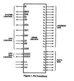
Z80-1.jpg

Larry
 
Last edited:
Hi All;
K1Atn, ldkraemer has made some good points, of things to try..
You are making good progress, Don't give up yet or so soon..
Yet, I wouldn't completely jump to conclusions, about the incompatibility of Your Z-80 Board.. Its is good that you checked out Ic's "T and U" , But did You get when the proper codes on the Data Leds..
Remember at this point You Don't need the Z-80 Board in the machine.. Also, You have checked out some of the Ic's but not ALL of them in the Front Panel and in the Z-80 CPU Board and in the Memory Board.. It only takes One to mess the whole system..
When You have a Low on the OutPut of IC "T" what do You show on the Data Leds and then when there Is a High on the Output what do the Data Leds show.. Same thing with the output of IC "U".. Remember that by turning on these IC's and turning them off You are creating the Codes for a Jump Routine (Octal) 303 000 000 or even the inverse 074 111 111 on the Leds and the various 7405's should be able to put that out on the Data Lines..
Then, as I stated Yesterday, You still need to follow the signals back from these two Ic's to the Switches.. And make sure that the 74123's are putting out the Correct Pulse Length.. Check the Resistors and Capacitors, for Breakage and or value change, and Replace when in doubt..
Also, I keep on forgetting to Ask, is Your Z-80 Socketed and is Your Front Panel Socketed ?? There is Good and Bad, no matter which way You answer for each.. If they are socketed, then make sure that the connections are good and not corroded from 40 years of setting around, and If they are not they when You have to replace something, You have to clip it out and put in another Part, and when putting in another Part I would socket them with "machined Sockets" they are better and more expensive, but they are worth it..
THANK YOU Marty
 
Last edited:
On my unit, the pin 11 that's supposed to show +5VDC shows no volts, pin 29 shows no volts, Pin 6 on my unit is hooked up to VI 2 according to my Altair's bus structure diagram instead of /CLK like you said it should be.
The rest you talked about are hooked up according to my Altair manual's bus structure also.
Pin 16 on my unit is not hooked up at all on the bus according to the bus structure. You said that /INT goes there.
Pin 17 is not hooked up at all on the bus according to the bus structure diagram. You said that /NMI goes there.
Pin 24 on my unit is hooked up to 02 according to the diagram. You said that /WAIT goes there.
Pin 25 on my unit is hooked up to 01 according to the diagram. You said that /BUSRQ goes there.
Pin 26 on my unit is hooked up to PHLDA according to the bus diagram. You said that /RESET goes there.

On my bus structure diagram pin 27 is PWAIT, pin 75 is PRESET, and pin 73 is PINT you say they go on a different pin so what do i do, and what do i do about the no voltage problem on pin 11 and how do i ground pin 29?
 
Hi All;
K1Atn, I think at least Partly, You are mixing up Z-80 pin numbers and Altair Buss Numbers..
Also, check a few other things, before making sure of something..
So, lets start with No +5 Volts on pin 11 of the Z-80..
First, make sure that You have counted the pins correctly, I have made that mistake before myself..
Next Go to the Regulator You have a 7805, So check that You have about +8 volts on one side and about + 5 volts on the other side of it, with respect to Ground..
Then Go to any other chip other than the Z-80 and on the top Right hand corner of most of the 14 pin or 16 pin Ic's locate pin 14 or pin 16 and check for the + 5 volts there, Check a number of them, and IF You get nothing either from the Regulator or from the Corner pin.. Then I would suspect that Your 7805 is Bad.. Before Rechecking the Z-80 itself, once You have the proper voltage coming out of the regulator, check other Ic's and then Recheck the Z-80 itself..
Once You have that Established, then we can go Point by point thru each of the other Signals that You have posted above, and Rechecking them one or two at a time..
I know that this can be overwhelming, but hang in there, and things will look brighter after some hand holding and Practice, with what is being referred to and what You are seeing..
Also, Take the Z-80 Board out of the Altair and "OHM" it from the middle pin of the Regulator to Both the Ground connection on the Altair Buss and to some 14 and 16 pin Ic's, only on pins 7 or 8 where most of the grounds are and on pin 29 of the Z-80 make sure You have that.. And do the same for the +5 pin on the Regulator, check with the Meter, that You have connections to pins 14 or 16 on most of the small ic's, and on the Z-80 on pin 11..
Once You have "THAT" done then we can go to the next set of points You raise in the above posting..
After turning my computer off, I had another thought.. So, I am back again..
With the Z-80 Board Plugged into the Buss, check that You ARE indeed getting the +8 volts to the Regulator and do the Same on the Memory Board.. Maybe, I doubt it, but it doesn't hurt to check.. That the Front Panel has the +8 volt coming to it and the Altair S-100 Buss Does not have the +8 volts coming to it, so check Both Boards !!

THANK YOU Marty
 
Last edited:
Okay i misunderstood, I thought you meant pin 11 on the Altair bus. Yes it shows 5v on pin 11 of the z80 CPU chip on the CPU board. The 7805 shows 8 volts on one side and 5v on the other just like you said it should. On the chip labeled WD8250-PL the voltage on pin 20 is 5v. Every single 16 pin IC shows 5v on pin 16. With the 7805's middle pin OHM'ed to ground (pin 50 and pin 100) on the Altair Bus it shows 0.24 ohms, and every single 16 pin IC when OHM'ed on pin 7 to the middle pin of the 7805 shows 0.09 to 0.16 ohms depending on the IC. pin 7 was the only one the ohmmeter lit up on. Also from the 7805's middle pin OHM'ed to pin 29 of the Z80 chip it shows 0.14 ohms. I am also getting connections from the +5v pin on the 7805 to the IC's and pin 11 on the Z80 chip. I also checked to see if the regulators are getting +8v, and they are indeed and so is the bus. The only socket on the bus not getting 8v is the first one in which pin 1 isn't getting 8v but every other S-100 socket on the motherboard is getting proper voltages including pin 1 on each one. I just don't plug anything into the first socket.
 
Hi All;
K1Atn, Ok, Good progress,
Now Look at the Questions You posted on Page 5 of this Blog, and the Schematic (page 96) that You posted Earlier, and see IF that Resolves most if not all of Your previous Questions..
If, so, then we can move on Back to the Front Panel again.. and as I stated in that post You need to Really check out the 7405's and make sure they are putting out as they should.. Take the Z-80 Board out, and make the outputs of T and U "high" and "Low" and make sure on the data leds that You see are putting out the proper Response.. Otherwise, You need to make it so that they do and are putting out the correct values.. And work Your way back to the switches themselves.. Once that is done, and we Know that the Front Panel seems to be working correctly, we can move on to the Z-80 Board and the Memory board itself..

THANK YOU Marty
 
Hi All;
K1Atn, I am going to Ask You to do something that seems Quite Strange, But, there IS a reason for what I am asking You to do..
Take out the Z-80 CPU card out from the Altair, And CAREFULLY Remove the Z-80 CPU IC.. And Place in a safe place, (Location)..
Take the Z-80 CPU Card with the Z-80 CPU Removed and Plug it back into the Altair..
Plug into the Z-80 Card the 8 pin Cable from the Front Panel..
Apply Power to the Altair, Do a Reset and a Stop, then with ALL of the Switches Down (OFF), Press Examine, it Doesn't matter what the Data Leds show..
Next Press, the Deposit Switch and then the Deposit Next, until You have advanced the Address lines about 8 times..
Then Press Stop and Reset, and press Examine..
Your Data Leds should show all Off, anything else and You have a Problem, with the Front Panel.. IF that works, try putting at Address '0000, Data '0000 and at Address '0001 Data '0001, etc up to all eight Addresses..
What You are Doing IS Using Your Front Panel to Write to Memory, WithOut the Z-80 getting in the way..
I tried it on My machine only it was with my 8080 CPU instead of a Z-80 Card, But the Principle would be the same.. And so should the output and the results..
Please let me know what Your results are..

THANK YOU Marty
 
I carefully took the Z80 CPU chip out, and put the boards back in (including the memory board) and connected the 8 pin cable to it. I turned it on and WO was lit up and so was every data light and every address light. I tried to do as you instructed i tried to do a Reset and a Stop, then with ALL of the Switches Down i tried to press Examine, then i tried to Press the Deposit Switch and then the Deposit Next, and then Stop and Reset, and tried to press Examine but absolutely nothing happened. The lights stayed the same and NONE of the switches did anything. When i put the CPU chip back in the switches started selecting again.
 
Hi All;
K1Atn, OK, Good..
Then, let me take a quick peak at the Z-80 Schematic, just to make sure that it should work with Your Board..
But, MOST likely there are/is problems with either the Front panel or the Memory Board..
For Now, let concentrate on the Front Panel.. Also, is the Front Panel "Socketed" or are the Ic's soldered in Directly ??
Go ahead and Take out the Z-80 chips and lets see if We can make anything work..
Check to see If pins 22, (ADDress Disable) 23, (Data Out Disable) and 53 (Sense Switch Disable) on the Altair Buss are all High, If any are Low, the Front Panel will not work..
Go check these and I will look at the Z-80 Schematic..
I checked there should be NO problem, also on the Z-80 Schematic pin 23 Data Out Disable is mis-labeled as pin 21..

Also, Try this, Completely take out the Z-80 CPU Board and turn on the Altair and see IF any of the Switches work, You WON'T be able to have anything of meaning show up on the Data Leds, since they are Disconnected, But, You should see the Address Leds Advance with both Examine Next and Deposit Next.. Then we know it is the Z-80 Board that has an IC that is Causing the Trouble and not the Front Panel..
If You have a Wire-wrap S-100 Board, You could wire in those 8 lines and completely take out the Z-80 Cpu Board, and then use the Front Panel all by itself.. Do You have an S-100 Prototype or Wirewrap Board with nothing on it or You could make it work for our purposes ??

THANK YOU Marty
 
Last edited:
Hi All;
K1Atn, I JUST REALIZED I MADE A BIG MISTAKE, WHEN I TESTED MY 8080 .. I FORGOT TO PULL OUT THE 8080, AND WHEN I DID LIKE K1ATN SAYS ALL THE LED COME ON AND NOTHING HAPPENS, JUST AS HE SAID..
SO, ALOT OF WHAT I SAID IN MY LAST POST IS NOT CORRECT, FOR NOW.. I WILL LOOK INTO IT MORE TOMORROW.. AND SEE WHAT I CAN DO TO MAKE IT WORK..
I APOLOGIZE, I AM SORRY FOR PUTTING YOU THRU THE EXTRA EFFORT !!!

THANK YOU Marty
 
It's ok Marty, I know you and all the other guys will get me through this :D I will await your response tomorrow.
 
Hi All;
K1Atn, Thank You for being so understanding..

But, MOST likely there are/is problems with either the Front panel or the Memory Board..
For Now, let concentrate on the Front Panel..
Also, is the Front Panel "Socketed" or are the Ic's soldered in Directly ??
Also on the Z-80 Schematic pin 23 Data Out Disable is mis-labeled as pin 21..
Going back to my previous post, have You done any of this ??
Now Look at the Questions You posted on Page 5 of this Blog, and the Schematic (page 96) that You posted Earlier, and see IF that Resolves most if not all of Your previous Questions..
If, so, then we can move on Back to the Front Panel again.. and as I stated in that post You need to Really check out the 7405's and make sure they are putting out as they should.. Take the Z-80 Board out, and make the outputs of T and U "high" and "Low" and make sure on the data leds that You see are putting out the proper Response.. Otherwise, You need to make it so that they do and are putting out the correct values.. And work Your way back to the switches themselves.. Once that is done, and we Know that the Front Panel seems to be working correctly, we can move on to the Z-80 Board and the Memory board itself..
THANK YOU Marty
 
Hi All;
I just Broke the Data Out Connector on my 8080 CPU Board, its fixable, with a few wires..
I am looking at my various Z-80 Boards, to see what I can use that has the ability to connect into my Data Out connector..
I have an IA 1010 (Ithaca Audio) or a North Star ZPB-A2.. And I have about 4 other Z-80 Boards withOut the connector..
Both the IA and the NS are not working..

THANK YOU Marty
 
Last edited:
Back
Top