• Please review our updated Terms and Rules here

CT-1024 Terminal Manual?

Looking at the display, you have serious hum/AC ripple problems.

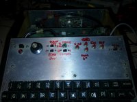
The switches that you have don't match anything on mine. You should have momentary contact pushbuttons for clear screen, line, etc.

So let's go back to zero on this.

First off, what shape (and in particular, the +5V output) is your power supply in? How much ripple do you detect?

Second, remember that the keyboard and display sections are completely separate. I assume that you have a UART card in there with an AY-4-1013, S1883 or TR1602 IC on it? It's completely normal for the screen to come up in garbage--there's no power-on preset for the display RAM. You should be able to clear it with the pushbutton that goes to pin 8 on J3. Similarly, you should be able to select which display page you're showing with the switch that grounds either J10 pin 1 or pin 2.

Similarly, the pushbutton that goes to J3, pin 2, is "forward cursor"; to pin 4, "backward cursor"; to pin 1, "home"; to pin 5, "line up"; and to pin 3, "line down". You might want to label them.

A little tip--you can significantly reduce the power consumption of the terminal by replacing the 6-2102 ICs on the display memory board with 21L02 or 91L02 chips. Those old 2102s devices and get pretty hot.
 
I don't know how to check for ripple.. but I did do a multimeter test off the +5V pole, and it is steady at exactly 5v. The other two are harder to get at but I'll try.

The pushbuttons appear to do nothing.. except one of them does sort of cause a 'reset' every once in a while.. but the screen returns to garbage.

And yes, my system has the optional serial board installed.
 
Did you loop back your serial (keyboard) output to the (display) input? That is, JS-1 pin 6 to pin 7.

Put your DMM between JS-1 pin 6 and ground? Do you see a pretty high negative voltage? If you press a key on the keyboard, do you see that voltage twitch?

To check for ripple, set your DMM to "AC volts", and then see if you get any reading across the various terminals. That big smear in the display is an indicator.
 
I'm using an analog MM right now.. I set the switch to ACV 10 -- and when I attach to the 5v+ pole, it goes to +22db?
 
Also, I may have goofed on the loopback.. I looked at the rs232 port on the back, found pin 6 and 7 and jumpered them.. but looking inside.. it appears the previous owner has this wired differently -- 7 has a wire to it but there's no wire to 6.
 
Okay, found the wire coming from pin 6 on JS-1 (if I understand correctly, you count from top left, left to right, from top to bottom.

I get -12.83V. No change at all with a key pressed.
 
Note: on the first test, I did not have 2 and 3 on the DB25 jumpered. When I connect pins 2 and 3 on the DB25 and then read voltage from JS-1 6, it comes down to -5.85V. But again, no change with pressing keys.
 
I tried removing the cursor board and shorting J3 pin 8, also J3 pin 2 and pin 1 per the assembly instructions. No reaction at all. I'm kind of wondering about this one switch that when flipped causes the entire field of characters to go away until you flip back again.
 
Well, I don't know what the switch connects to, unless it's to J10 1-2.

You can also ground pin 8 of JS-1 on the serial board to echo the keyboard characters (that bypasses the level shifting circuitry).

Do you perhaps own a logic probe or oscilloscope? A VOM is not much of a tool to do trouble-shooting with, particularly on something this old.
 
Last edited:
Okay I think I solved that switch (and am solving the rest).

The mystery switch that causes the characters to disappear connects to pin 6 of 10 (Cursor ON/OFF).

There is a second mystery switch that goes to pin 5 of the Serial board's I/O connector.

A third switch, right below it, connects to pin 8 of the serial board I/O connector.
 
Answered my own question by re-checking JS-1 pinouts.

The top switch goes to pin 5 of JS1 which is Ground for Receiver OFF
The bottom switch goes to pin 8 of JS1 which is Ground for Echo OFF.

So flipping the top switch to where both its poles have contact means Receiver OFF, I take it? Same for Echo?

So if Echo OFF is grounded, nothing will come back to the screen when I type..
 
I'm assuming that the keyboard is plugged into JS-2 on the serial interface board. But yes, Pin 8 of JS1 should not be grounded for echo operation.
 
Yes it's plugged into the connector marked 'Keyboard' on the serial board which I assume is JS-2.

Okay, so I think I sorted out my push buttons:

Button 1 - Pin 3 of JMC 1 = Cursor Down
Button 2 - Pin 8 of JMC 1 = Ground
Button 3 - Pin 9 of JMC 1 = Home Up
Button 4 - Pin 5 of JMC 1 = Erase to EOL
Button 5 - Pin 4 of JMC 1 = Erase to EOF

Big green stalk switch = Page 1 or Page 2

The dial must be for baud.. so I think I've got all my switches figured out. Now if only I understood how they worked.. :)
 
20140927_174058.jpg

When the cursor switch is on.. that is when the garbage screen disappears. But I've tried hitting cursor down a bunch of times and typing.. nothing. I suspect hidden up top is that strange single line of random characters.
 
No, I was after a volt- or millivolt reading--I don't know what your VOM is using as a reference; it could be somewhere around 200 mV pp, but that's hard to say. What reading do you get when you measure 6.3VAC RMS?
 
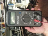
This is the DMM I have.. not really sure how to test as you suggested. ;) I've gotten better theblast year with continuity, resistance, etc.. but we are into uncharted territory for me with AC hum, etc. ;) If you dont mind guiding me a bit I'm sure I'll catch on (or catch fire :)).

20140927_201736.jpg

I shoulf mention under the red connector its marked AC, and under the black.. V with the OHMs symbol.
 
It looks as if the only AC scales on the DMM are for 200 and 750 V. Fine for the home electrician, but not so much for digital circuits.

An inexpensive logic probe may help you. It can detect the difference between a steady level and a pulse.

But honestly, I'd probably not jump into this thing without an oscilloscope. Then it'd probably be a matter of a couple of hours of checking.

Yeah I kind of figured. It'll be a while yet before I have a scope and so much of this is yards above my head. It'll take a long time to get there.

Is there any point to just trying cap replacement? I'd be up for that.. although I cannot for the life of me find a 5000mfd 10v can type with just two legs.
 
Back
Top