• Please review our updated Terms and Rules here

Science of Cambridge (Sinclair) MK14

dansretropod

Member
Joined
Jul 2, 2012
Messages
34
Location
UK
Hi all,

Bit of a longshot this as I know this is a very rare computer but:

Does anybody out there know how the keyboard on a Science of Cambridge MK14 is constructed? I purchased one recently and the keyboard seems to be missing the contacts that go into the "Circle Domes" mentioned in the training manual. Which means pressing a key doesn't do anything.


Thanks!

I had an issue 2 kit, the keyboard consisted of a "conductive" rubber pad topped by a piece of flat plastic printed with the key functions, with issue 4 boards came a set of plastic buttons, then there was a metal plate to hold everything down, this was all held in place by 4 plastic pegs passing through the assembly into the PCB.

Of course many people simply connected a better keyboard using the side connector.

P.S If you have the manual there is a drawing inside that shows all this, but as you are asking, I will assume you do not have the manual.

There is a manual on-line and I will update this post with a link when I find it.

Here is a pdf http://s400081762.websitehome.co.uk/manuals/main.htm
 
Last edited:
Beware on the circuit diagram (however) that the four key lines going into IC11 do not emerge on data lines D4..D7 as implied.

Keys 0-7 appear on D7; keys 8 and 9 appear on D6; keys GO, MEM, ABORT and TERM appear on D5 with the remaining keys (A, B, C, D, E and F) appearing on D4.

If you are repairing the existing horrid keyboard then this shouldn't matter. If you are thinking of adding an external keyboard then it may.

Page 7 of the MK14 manual is what you are looking for.

Did you buy the MK14 off e-bay? I noticed a guy had one for sale the other day and it disappeared from the auction before the end was due.

I had an MK14 many years ago and am in the process of building a home-made breadboard version to recreate the 'experience'. Well done on acquiring one though.

I have also just completed an FPGA version (complete with the VDU interface and everything) that I will be putting on opencores.org presently once I can shake the bugs out of it.

I am also in the UK (Worcester) so if there is any information you want regarding the MK14 (and I can be of help) just PM me.

Dave
 
I used to have an assembler for the MK14 but lost it over the years, it was just 2 sheets of paper with the machine code listing and instructions on how to use the assembler, do you happen to have a copy or know if it is on-line somewhere?
 
Thanks for the info guys and the links, they've been very useful.

I had an issue 2 kit, the keyboard consisted of a "conductive" rubber pad topped by a piece of flat plastic printed with the key functions

The MK14 I have is also an issue 2, so I'm just missing the "conductive" rubber pads you mention for each key. Any suggestions for suitable replacements? I guess I could make them myself.

Did you buy the MK14 off e-bay? I noticed a guy had one for sale the other day and it disappeared from the auction before the end was due.
I did indeed, last week. It was listed as a buy-it-now and I arranged to go and see it on the Saturday and purchased it then, quite lucky really to find one of these with a buy-it-now that hadn't already been sold.

It seems to work, just the display shows incomplete digits but I think if I swap some of the IC's related to the display on there it might fix it.

Thanks for your help!

Dan
 
Thanks for the info guys and the links, they've been very useful.


The MK14 I have is also an issue 2, so I'm just missing the "conductive" rubber pads you mention for each key. Any suggestions for suitable replacements? I guess I could make them myself.


I did indeed, last week. It was listed as a buy-it-now and I arranged to go and see it on the Saturday and purchased it then, quite lucky really to find one of these with a buy-it-now that hadn't already been sold.

It seems to work, just the display shows incomplete digits but I think if I swap some of the IC's related to the display on there it might fix it.

Thanks for your help!

Dan

It was a single peice of rubber the same size as the whole keyboard, you really would be better off with an external keyboard.

A couple of years ago an mk14 was listed on ebay. but if you read the description (which I did), it turned out that the rubber pad was the only part of the mk14 that was on offer!
The listing was removed.
 
Dan,

You might find this website useful "http://www.zoflex.com/". I am sure there is a comparable UK company if you can find them.

If it is complete digits that are missing then this could be down to either IC12, IC13 or the display itself (or the flexible cable linking the calculator display to the PCB - which has been known to fracture). If it is IC12 or IC13 then some of the keys will probably not work either (as these ICs are not only used to drive the display but also scan the keyboard).

If individual segments are missing - this could be down to IC9, IC10, IC14 or IC15. IC9 and IC14 handle segments 'a', 'b', 'c' and 'd' whilst IC10 and IC15 handle segments 'e', 'f', 'g' and 'dp'. (Or the cable again)...

Dave
 
If it is complete digits that are missing then this could be down to either IC12, IC13 or the display itself (or the flexible cable linking the calculator display to the PCB - which has been known to fracture). If it is IC12 or IC13 then some of the keys will probably not work either (as these ICs are not only used to drive the display but also scan the keyboard).

If individual segments are missing - this could be down to IC9, IC10, IC14 or IC15. IC9 and IC14 handle segments 'a', 'b', 'c' and 'd' whilst IC10 and IC15 handle segments 'e', 'f', 'g' and 'dp'. (Or the cable again)...

Thanks for the info. Dave, very helpful, I've got some on order, will give them a try when they arrive.


Thanks,

Dan
 
I had an issue 2 kit, the keyboard consisted of a "conductive" rubber pad topped by a piece of flat plastic printed with the key functions, with issue 4 boards came a set of plastic buttons, then there was a metal plate to hold everything down, this was all held in place by 4 plastic pegs passing through the assembly into the PCB.

Hi
Please can you make high resolution scan of MK-14 unpopulated PCB (both sides) and send to my email? 300 or 600dpi will be great.

Thank you
 
Just reading this thread again makes me want an MK14 again, I have 5 SC/MP chips and am thinking of building a system with 3 SC/MP chips sharing the bus as they were designed to do, maybe even having the VDU on board but I read somewhere that the VDU reduces program execution speed by 70%, I don't know if this is true, but if anyone has experience of using the VDU maybe they could confirm or deny that for me.
@Fastah, If anyone can supply a PCB scan for you, I would be interested in buying a PCB if you intend on making a batch, I am sure others would also buy one considering the price MK14's go for on ebay.
 
There is a description of an MK14 reproduction here: "http://www.8bity.cz/replika-mk14/jak-jsem-stavel-science-of-cambridge-sinclair-mk14/" (including PCB).

Note that there are a couple of tracking mistakes in the keyboard section.

I also have a few SC/MP chips and would love to make an MK14 myself. If anyone is thinking about making a PCB - count me in for a couple...

I have prototyped up the MK14 (and it's VDU card) in a Xilinx Spartan FPGA in VHDL if anyone is interested. I have a couple of problems I am slowly shaking out...

The VDU card required that the SC/MP crystal be lowered from 4.43 MHz (good old PAL colour burst) to 4.0 MHz. It also 'shares' the memory with the SC/MP microprocessor - so the SC/MP can be held up if the VDU card is accessing the memory. The VDU manual states that this may slow the processor down by about 6%. It is also slower as a result of the slower crystal frequency. It will make a difference - but I can't see as though a 70% reduction is valid.

Dave
 
Hi, nice to see there is still some interest in this old machine.

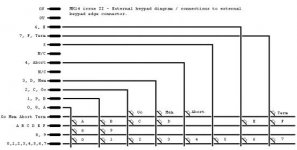
It's been a while since the OP's original query, but keypads are often the bane of these machines due to the fact that the originals were so bad that they were often removed or replaced with something more reliable but non-original. I have a nice diagram of the circuit for an external MK14 keypad and its connections to the lower right 'external keyboard' edge connector - I'll dig it out and post it here when I get a chance.

With regard to the VDU, I still have one along with my MK14 (and the cassette interface as well).

The VDU wasn't a great success. It required connections to all of the address, data and control bus signals as well as a handful of I/O signals for things like graphics / text mode control and white on black / black on white selection. On boards before about issue IV (mine is issue II) the bus connections were not available on the top edge connector, so installing the VDU involved plastering wires all over the MK14 board, resulting in an unholy looking mess.

Even with that problem overcome, the VDU consumed 512 bytes of the system RAM (because it had no RAM of its own) and held the processor in the HALT state for a considerable portion of the time while it read screen data from the RAM area being used as screen memory. On a standard, fully expanded MK14 this left just 128 bytes of RAM which wasn't being monopolised as screen RAM.

I used it that way for a while, but then disconnected the VDU from the MK14 and restored the MK14 as nearly as possible to its original 'clean' standalone form, and it has been maintained in working order ever since. The VDU was relegated to being an interesting museum piece for more than 30 years until I took pity on it last year (2013) and lashed up a companion controller board for it, so I could run it up and see it working without having to reconnect it to the MK14. All it does at the moment is to feed the VDU's voracious demand for screen data: The test software currently just fills the RAM with a static text message to display on the screen. The plan is to write a 'demo' of sorts with some scrolling text and animated graphics if I ever get the time.
 
Last edited:
Took a while, but here it is, my diagram for the MK14 external keypad and its connectons to the edge connector on the lower right hand edge of the board. Apologies, but the forum engine seems to have downsized it, although it is still just about readable.

I can appreciate that it's been a long time since the OP posted his query but other people may surf onto the thread from time to time in search of the same information. Note this info applies to the issue II MK14 especially, since that's what I have and that's what it was devised for. Later marks may have made use of some of the 'redundant' connections for other purposes - it always seemed a bad idea to me that the reset line wasn't also brought out to this edge connector.

mk14_keypad_v2.jpg
 
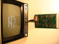
I still didn't get around to writing the promised 'demo' for my MK14 VDU card as promised two posts back. It's connected to a PIC 18F452 microcontroller which first loads 512 bytes of its internal RAM with sensible data, and then starts serving the RAM data to the MK14 VDU. Although it spends most of each video frame doing that, in the periods in between, it is free to manipulate the contents of the RAM so it would be possible to get it to do some animations or some sort of game - some sort of moving imagery anyway. That is the eventual aim if I ever get around to it.

In the meantime, here's a photo of it displaying a simple information message on an appropriately vintage 10" black and white TV.

IMG_6611.jpg

As I mentioned previously, I still have the MK14 as well, although it is no longer paired up with the VDU card. A while ago, I posted a youtube clip of SC/MP code being uploaded to it using a Raspberry Pi and a home made serial hex downloader to keypad connector interface. If you haven't come across it before, have a look at it here:-

http://www.youtube.com/watch?v=j1WSy_ueX34

To go straight to the interesting bit, skip to about 1:58.
 
One quick question - where did you get the keys from (in particular the key tops) for your MK14 keyboard?

Dave
 
One quick question - where did you get the keys from (in particular the key tops) for your MK14 keyboard?

Dave

I made the keypad you see in the clip when the MK14 was quite new, in other words, more than thirty years ago. Unfortunately, like many MK14 owners at the time I saw no reason to preserve the original keypad (it really was terrible) so I lost all but one of the component parts over the years. All I have now is the large square conductive rubber mat, arguably the most important part. At some point I may try to see if I can get a new upper frame and lower separator laser-cut - the key legend sheet I could probably reproduce myself. But for the time being, I don't think it looks too bad with the keypad it has.

Anyway, the key switches and key tops were sold by Maplin (electronics chain store in the UK similar to Radio Shack in the USA, for readers who are not in the UK), but they stopped stocking them a long time ago. Radio Spares (RS), also in the UK were stocking the same type of switch and switch cap right up until the late 2000's but they don't seem to do them any more either. (I have been looking because I wanted to have some spares). I believe they were made by C&K but unfortunately that's all I can remember now.

The key tops were plain when I bought them - I lettered / numbered them using 'Letraset' rub-down transfers - it took roughly 3-4 attempts for each key top before I got the letter / number down in one piece and in more or less the right place. if you look carefully you can see that one or two are not perfectly centred. I then fixed / sealed them with a layer of clear matt polyurethane varnish. I wouldn't have the patience to do it all now.

Nowadays, if you bought some cherry key switches and some plain keytops, you might be able to get the keytops engraved by a jeweller or a signwriter for a reasonable price. Or, if you went to a maker fair you might find someone who can work out a way to print the key legends directly onto plain key tops for you and make them permanent by printing a layer of clear sealant over the top.

Incidentally the keypad was built on ordinary stripboard / veroboard, but before I fitted the switches I placed a piece of black modeller's 'plasticard' over the top of the veroboard and cut it to exactly the same size - then I drilled through the black plastic card in the right places to let the pins of the switches pass through it and through the veroboard before being soldered on the copper side of the veroboard. The wiring from the keypad to the MK14 is all hidden under the keypad, lightly tack-soldered onto the tracks in the appropriate places.
 
Not sure if this will cross over with my other reply as my posts are being moderated at the moment (?), but I have now managed to dig up the details of the switches I used for the red / blue keypad on my MK14.

The switches are C&K model 'MDPS LFS' and although Maplin and RS no longer stock these, Digikey still supply them.

The plain keytops come separately in a range of colours each with its own C&K part number, so for example the red keytops are "BTN MDP 40" and the blue ones are "BTN MDP 60". The grey ones are "BTN MDP 20". I would have used those for the 'Go', 'Mem', 'Abort', 'Term' keys if I had been able to get them at the time.

As an alternative you could consider another C&K type, the "KS11R......." series. Like the ones I used these fit exactly onto stripboard / veroboard without any extra drilling and will pack perfectly alongside each other in a column / row arrangement with no gaps between the switches. Unlike the MDPS series, however, the keytop is built in to the switch so you have to order the switches in the colours you want in the quantities you want them. This series are also significantly cheaper than the MDPS series. I don't know what the full colour range was on these, though. Digikey currently have them in white, black, red and blue and I can also see one UK 'auction site seller' offering blue and yellow ones.
 
"...nice to see there is still some interest in this old machine." - troubleshooting?

"...nice to see there is still some interest in this old machine." - troubleshooting?

Just dug out my MK14 from the loft. When the original keyboard gave up the ghost I built the circuit board into an old Calculator body (Olympia CPA 1200), wired the keyboard up to the MK14 external connector and extended the display leads to make the display visible in the calc body. Worked fine with much quicker keyboard entry. :)

It also has the cassette recorder board attached. Got the manual and separate sheets for Tape Interface, Writing a program, VDU instructions, and Addendum to Section 5. I can scan if anyone needs a copy (including my own comments, annotations and scribble on though!).

However....Just powered it up and the display didn't show the row of dashes ---- -- as normal. Instead it displayed what looks like a a 6 a ' ' 70.
Hmm.
I intend to re-seat all the chips, check for dry joints etc etc and see what transpires.
In the meantime, if anyone has any tips regarding what else I can do to get it to work, I'll be very grateful. :)

btw - Someone has one for sale on Ebay for £1500.
 
Back
Top