• Please review our updated Terms and Rules here

IBM 5154 Troubleshooting

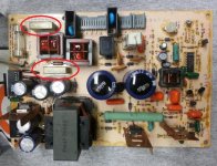
I pulled the PS back apart and discovered it was C11 that had released its magic smoke. Assuming something must be wrong to have popped a new cap, I went back through the board again with the scope and meter, but didn't find any problems. I replaced C11 with an identical 47uf 50v 105C cap, put it back together, and it works great! It seems strange to me that a new cap was faulty, but I have no other explanation.

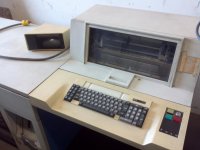
EGA-5154.jpg

I do have one final PS related question though. The only part of the SAMs documentation that doesn't make sense to me is the instruction to measure the output of IC2 (an LM7812 voltage regulator), and adjust RT1 (a 1K ohm pot on the PS board) until it reads 12v. Unless input to the regulator drops below 14.5v or so, it's always going to read 12V at the output, so I'm not sure where to set RT1. I adjusted it until the regulator's input (cathode side of D17) was ~14.6VDC. It hasn't blown up yet, but it's only been on for a couple of hours...

Anyway, I think that's a wrap for now. Thanks everyone for all of the helpful suggestions!
 
I use sheet-metal screws.


Possibly a line suppression capacitor.
See http://www.minuszerodegrees.net/failure.htm

If it is a line suppression capacitor, then I suggest that you replace both (high failure rate item if old).

View attachment 24404

Thanks for the ideas, and apologies for the slow and out of context replies (my post count is too low for instant replies). The line suppression caps are intact, but as mentioned, it was C11 that blew. So far, the third C11 in as many days is holding up nicely as I've been using the monitor all evening. Thanks again!
 
I do have one final PS related question though. The only part of the SAMs documentation that doesn't make sense to me is the instruction to measure the output of IC2 (an LM7812 voltage regulator), and adjust RT1 (a 1K ohm pot on the PS board) until it reads 12v. Unless input to the regulator drops below 14.5v or so, it's always going to read 12V at the output, so I'm not sure where to set RT1. I adjusted it until the regulator's input (cathode side of D17) was ~14.6VDC. It hasn't blown up yet, but it's only been on for a couple of hours...
I think someone at SAMS goofed.
If I had written the RT1 adjustment procedure, the monitoring point would be the 154 VDC line (goes to the cathode drivers), with adjustment to get 154 VDC.
 
Hi folks,

How easy is it to remove the PSU for repair as mine went up in smoke too ...

I'm comfortable with fault finding electronics, soldering and repairs etc. but just a bit nervous working inside monitors due to the high-voltages!

Do I need to discharge the CRT before attempting to remove the PSU?

Thanks for all the info in this great thread btw!

Stewart
 
I'm comfortable with fault finding electronics, soldering and repairs etc. but just a bit nervous working inside monitors due to the high-voltages!

Do I need to discharge the CRT before attempting to remove the PSU?
I see no need.

How easy is it to remove the PSU for repair as mine went up in smoke too ...
1. Leave the 5154 disconnected from mains power for an hour (to be safe).
2. Unplug the three cables that connect to the side of the PSU cage.
3. Unscrew the (10 or so) screws that hold the PSU cage in position.
4. Move the PSU cage upwards (because of the hidden connector).
 
Hi folks,

How easy is it to remove the PSU for repair as mine went up in smoke too ...

I'm comfortable with fault finding electronics, soldering and repairs etc. but just a bit nervous working inside monitors due to the high-voltages!

Do I need to discharge the CRT before attempting to remove the PSU?

I once worked with a man who had repaired TVs at an earlier job. I notice that someone said you don't need to discharge the CRT, but I clearly remember that guy at work showing me how to do it and saying it was very important to do it. He said the voltage was 10,000 volts, which would have been stored in a capacitor.

Please take a suggestion for someone who wants to preserve vintage computer enthusiasts in addition to the ancient iron and find a TV repair shop, tell them the manual for the 5154 is for sale from Sams (or buy it and offer to let them use it), and ask them if they will attempt the repair. I have such a shop in my city, it is located in a neighborhood where the rent is less than average.

Sean
 
I notice that someone said you don't need to discharge the CRT
Under certain circumstances.

I can see now that I needed to have put more thought into my simple "I see no need." response, because it can be taken out of context.

I once worked with a man who had repaired TVs at an earlier job. I notice that someone said you don't need to discharge the CRT, but I clearly remember that guy at work showing me how to do it and saying it was very important to do it. He said the voltage was 10,000 volts, which would have been stored in a capacitor.
The capacitor is the large part of the CRT. One side of the capacitor is a lining within the CRT, and the other side is the lining on the outside of the CRT. The outer lining is connected to the chassis.

The KV (relative to the chassis) is on the lining within the CRT, and at the CRT's anode cap, and in the lead that runs from the anode cap down to the flyback transformer.

If I am going to replace the CRT or flyback transformer, then I will definitely discharge the CRT beforehand.

The flyback transformer is soldered to the main board, so if I am going to remove the main board, I am going to have to disconnect the flyback transformer from the CRT, another requirement to discharge the CRT beforehand.

But for a lot of other actions, I see no need to discharge the CRT.

For some people, their improper method (procedure and tools) of discharging the CRT would be putting them at risk. For example, I can just see someone getting a blade screwdriver, inserting it under the flap to touch the anode, and then working out how to connect the screwdriver shaft to the chassis.

So, in my opinion, for certain repair actions, discharging of the CRT is possibly putting people at unnecessary risk.
 
Hello Everyone,

I have a new 5154 problem to present the experts here. I recently acquired a 5154 over Ebay. This monitor had the standard horizontal and vertical jitter associated with bad electrolytic caps. I replaced all of the caps, and what I have now is very strange. I'll show pictures of the red, blue and green patterns from Checkit and the corresponding voltage node from the RGB driver circuit. Their seems to be timing and voltage amplitude problems in the signal that cause the intensity and duration of the bits to change on the screen. The pictures of the screen are tough to see, because the persistence of the phosphor seems to average out the intensity changes for the picture. If you look carefully, the intensity differences are in all of the pictures; along with the geometry changes...i.e. I turning into ). But, here are the pictures. I set the cutoff voltage for the blue picture much higher to illustrate the intensity changes of the dots. Red and Green are closer to a normal bias cut-off voltage.


Red Raster Picture
Green Raster Picture
Blue Raster Picture

Red Driver Voltage Waveform
Blue Driver Voltage Waveform
Bias noise, blue channel. Horizontal Scan line bit.

When looking at the Blue Driver waveform, you can see that there is quite a bit of noise on the bias, compared to the Red Driver Voltage Waveform. Green shows the same noise as Blue. As well, when looking at the expanded view of the bias noise, you can see the varying width of an individual bit, and the bias noise.

I've replaced all of the caps, and all of the semiconductor content of the driver board. The power supplies are clean on input 154V and 12V. Horizontal and vertical pulse on the connector to the driver board are similarly clean.

I don't understand why only the red channel has little noise. All channels are showing the different intensity (ringing) and width of the screen data.

I've also disconnected the driverboard from the crt board to see if there were any driver issues with the CRT. The waveforms stay the same with or without the CRT.

I'm looking to see if anyone has a picture of a "normal" horizontal scanline. I would like to see a couple viewpoints:

1. From the bias noise perspective.
2. Does the bit data ring as much as I am seeing?

Let me know if anyone wants more information / scope shots or data points.

Let me know if you have any ideas!

Thank you,

Chris V.
 
I'm not following what you're seeing. The crosshatch patterns you show check for focus, geometry and convergence of the 3 colors with respect to each other. If you think you have varying intensity
across the screen horizontally then a solid pattern will reveal shading issues. How about showing pictures of solid red, green, blue and gray rasters? Also maybe just white text on black background?
Set you RGB cutoffs to produce a comfortable white screen. Analyzing video from an overall perspective might reveal more clues to the problem.
Analyzing waveforms on a scope requires a color bar type pattern. Crosshatch signals will be a blur.

Ok, I have done that before, and I can re-setup to give the pictures you want. I'll get them posted tonight.

BTW, the text being shown in the pictures is white text, with the cut-offs turned to minimum on the other 2 channels.

It's been difficult to analyze. There are slight timing variations going on between the channels. I originally thought that this was convergence. I am now more into timing differences and noise (this is why I was looking for the picture of the driver voltage on a working monitor). For instance, the amount of bend on the letter h in screen text "Graphics" from each primary color differs (Red is worse with the most bend, green seems to be the best). This produces a very blurred image; with lots of red bleeding through on the weak bits from the other primaries. Then combined with the intensity differences, you see blurred white letters with a red hue, and occasional complete misalignment.

When I received this monitor, there were several drive transistors blown from the output drivers to the pre-amp stages, along with the bad electrolytic caps. I have also re-flowed the solder joints. I have replaced all of the silicon content on the driver board; including the bipolar ROM TBP28L22N. I have replaced the 1/4W resistors on the heated output section (brown to black) of the board as well.

I'll post pictures tonight.

Chris V.
 
>there were several drive transistors blown from the output drivers to the pre-amp stages

If it's that catastrophic, it's usually from an arc in the neck of the CRT. I've seen that in IBM CGA monitors. Unfortunately, it's a bad tube and might reoccur.
If you ever hear a snap sound, one thing to try is leave it powered off, lay it on the face of the CRT and gently tap the neck of the CRT with the handle of a screwdriver.
Any loose particles would fall into the bell of the CRT.

> the amount of bend on the letter h in screen text "Graphics" from each primary color differs.

The bend, of course, is from the font but as to why it differs between colors could be caused by differences in focus between the color guns. Green is the center gun and highest intensity so
usually focuses the best. If the focus control isn't epoxied, you could try rocking it to see if it changes the appearance of the bend. When a CRT is failing, the red has a tendency to bleed horizontally.
A combination of adjusting the SCREEN control, FOCUS and the driver controls might be able to minimize the bleeding. If you get a good focused photo of white text at low intensity, we should be able to tell the difference between video smear (a video path problem) and bleeding (a CRT focus problem)

Hi retrogear,

I'll use my SLR Camera to take the pictures tonight. It will yield better results than my cell phone. Are you talking about the Focus knob on the side of the flyback?

I haven't heard any arcing or other snaps coming from the monitor; although, I am worried that the tube may ultimately be the issue. Red bleeding horizontally may be one way of describing what is happening.

Pictures coming.

Chris V.
 
>Are you talking about the Focus knob on the side of the flyback?
yes. A control labelled SCREEN may also be there which sets the screen grid bias for the CRT and greatly affects the cutoff for brightness.
If a manual exists, there will be instructions how to set all the bias controls. Even if the tube is failing, tweaking adjustments and just using
a lower intensity could look good for years to come.
 
Ok, here are some pictures taken tonight. I had to lower the brightness in order to have the camera not saturate the pixels. But, these pictures are representative of the problems.

Text with cut-off bias ~100V
Noise in Text Screen
Mostly White graphic background
Blue background with grey text
White raster with cable unplugged

Let me know if anyone has any ideas…mostly looking to determine if this is an electronics problem versus a worn out screen.

Retrogear, there is no knob labeled screen near the focus knob on the flyback. The screen control is a a pot on the board plugged into the end of the crt. I measured this around 350V.

Thank you,

Chris V.
 
OMG wow, that's definitely NOT a CRT problem. You have a high frequency component in your video signal. I'm guessing the high frequency ripple is coming through the power supply. Do you have a schematic? I'm looking at one
now. The scope waveform from your previous post 'bias noise, blue channel' shows the high frequency ripple. Get that triggered up on your scope and increase the scope amplitude to get a good wave, then put your scope on the power supply lines. Use AC coupling, we are not worried about DC voltage at this point. The power supply normally runs at a high frequency. According to the schematic, 2 millisec per division gives you one complete sine wave. If that's the frequency of the ripple in that blue waveform, then chase it back to the power supply lines that feed the video driver / output circuits, I would think like the 12v supply. A scope should easily track the source of the ripple. Maybe one of the caps you changed is wrong value, etc. It's easy to miss a decimal point when looking at a value. Good luck.

Larry G

Ok, when I get home tonight, I'll re-look at the power supplies coming into the board with respect to the noise on the blue channel. I had already done this looking at 12V and 154V supplies. However, I was DC coupled, and may not had enough vertical resolution. So, I'll do this AC coupled and post shots. I previously looked at the horizontal and vertical sync coming through the connector. This is fine without a substantial noise component. One component I didn't check / replace as well is the 7805 regulator.....

One thing that bugs me is the cleanliness of Red versus Blue channel.

More info to come tonight.

Thank you,

Chris V.
 
Back
Top