• Please review our updated Terms and Rules here

IBM 5151 Green Screen Monitors: Simple Checks

mmruzek

Experienced Member
Joined
Sep 28, 2011
Messages
227
Location
Michigan, USA
Hi,

Well, the last of my three IBM 5151 monitors has bit the dust. My last one served me well for many years... it's held together with duct tape after being hit by a fork lift by the previous owner. I'm working on a new project called the XT-Retro and would like to get one of these monitors back into a functional state. However, I don't really like working on monitors because of the high voltage, etc. I'd appreciate a few ideas for simple things to check. For example, are there any fuses inside? Any other simple checks? Thanks!

Michael
 
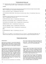
There is a SAMS Photofact for the 5151, the basic troubleshooting page is attached below......

If you provide more details about the symptoms you'll get more help from the forum :)


5151basic.jpg
 
I am in the same situation, my 5151 died last month and I have no experience repairing CRTs. First I'm learning how to discharge the tube and what safety measures should I take while manipulating the innards.

In my case, the monitor started to make a thin-intermitent-electric noise (don't know how to describe it precisely) while the image shrunk also, after 10 seconds the image dissapeared and a burnt smell came out.
 
For what it's worth - the circuit diagrams are available and these monitors are very simple. So if anyone was ever going to repair a monitor I'd start with one of these. I learn a LOT doing one of mine (non-IBM but similar design).

For testing them, I just plug them in to a computer with the proper port, and see what happens.
 
I am in the same situation, my 5151 died last month and I have no experience repairing CRTs. First I'm learning how to discharge the tube and what safety measures should I take while manipulating the innards.

In my case, the monitor started to make a thin-intermitent-electric noise (don't know how to describe it precisely) while the image shrunk also, after 10 seconds the image dissapeared and a burnt smell came out.
That might just be the flyback transformer.

The 5151 is very simple. You have video and sync amplifiers, the CRT driver cirquit, and a linear powersupply. Not too much that can go wrong.
 
Hi, Thank you for the SAM's Photofacts page! It was very helpful. I found that the soldered-in fuse (0.75A) is blown and one of the 4 power supply diodes is testing bad. Looks like there is enough space to get in there with my soldering iron and attempt a fix...

Willl mention: The 'secret' to getting the case open was finding the 2 screws on the top side of the monitor near the front. They are hidden by plastic covers, which in my case had discolored to the point of being obvious. Will also mention that there is 13KV+ voltage inside these things, so this repair requires attention to safety.

Michael
 
If that diode is measuring as 'shorted' then it would certainly cause the fuse to blow !
 
I opened my dead 5151and this is what I found:
With the power connected and the db9 video unplugged, the CRT heater doesn't glow but the voltages in the regulator are correct.
If I connect the video cable and power on the computer, the 5151 starts to make an electric noise and a smell like a burned chip. The heater doesn't glow either.
What could it be?
 
The simple answer is follow your nose. You'll have to take the back off the display. The odor will be quite strong on the failed component so don't power on again. With the 9 pin monochrome displays, the high voltage is activated from the horizontal drive on the pins so you don't have HV until you apply signal from the PC. Unfortunately, I'm guessing the HV transformer itself will be what is burning. You may or not visually see what's burned but again sniff around and looked for a charred component. If it's the HV transformer you might see a bubble or some melting plastic but your nose will be your best guide. When you
get it open, if it's not obvious post some good pictures of the component and foil side of the boards. Oh and look at the circuit traces. Some times a solder crack can actually arc and burn.

Also, typically on monochrome displays you can't see the heater glow unless you have the room lights off. It isn't bright like a color display plus color has 3 cathode heaters. But again troubleshoot only with power
off. It will only burn more until failure.

Larry G
 
Last edited:
You were right, turning off the lights and looking to the heater I can see a tiny orange glow. I was expecting something like this.

Following my nose, I think the odor comes from the flyback or near it. Are there flyback replacements for this monitor?
 
I was going to say "not a chance" but maybe?
The part# is 74730102538 and Googling gets some hits but you'll just have to inquire, I guess.
Do you do soldering? It would be 7 or 8 large pins thru a circuit board which would be easy. The HV lead to the CRT anode is just a spring clip.
There is a G2 wire (screen) and G4 (focus) wires to the socket on the CRT that would have to be soldered.
If you do this or someone for you it requires a technique called "ball soldering" where you build the solder into a ball shape on the lead to prevent arcing.
That might not be required for a monochrome CRT but definitely on color CRT's because higher voltages.
Or there might be just some kind of spring clip to insert the wire. I haven't done one on that particular display but have repaired many CRT's
in my past career as a service technician. Probably information overload for you at this point but good to know what to expect and for others
reading this.

Larry G
 
Last edited:
I've had the voltage regulator on mine fail once. Don't know if this is a common fault or not, but you might want to check the supply voltages before installing a new flyback.
 
Yes, changing a flyback is pretty drastic. If you're sure the smell is coming from it you could also check with an ohmmeter across the diodes D505,D503,D504 since those provide power from the flyback windings. It there was a short it would cause extra load on the flyback making it run hot and smell. I would think a voltage regulator feeding the flyback if shorted would blow the fuse but many possibilities exist.
I thought you said you checked the supply voltages but maybe I mis-read.

Larry G
 
If you worked with electronics long enough you can even tell by the smell i guess. I had that computer with a sizzling and smell coming from it after an unsuccessful attempt to turn it on and my workmate was like "Ah smells like roasted capacitor" and it was indeed a capacitor. But yeah a multi-meter is really helpful if you don't have that kind of nose.
 
I can still smell it from memory :p
Sometimes we used to do what's called the 'smoke test' if there was no other way to find the short with measurements. Obviously I don't recommend it here since it can create more damage.
I'm not saying his flyback is bad. There is virtually no way to test a flyback except with a test instrument called a 'ringer' but who has one of those anymore? Also the ringer would only check the transformer windings
but since the use of solid state circuits all flybacks have an integrated high voltage rectifier, focus rectifier, voltage divider which cannot be tested other than visually looking for burning or "odor". I doubt my nose
could detect it anymore :p

Larry
 
retrogear,
AH Yes, the Ring test of an Inductor or Transformer. It's been years since I used a Square Wave Generator and a GIMMICK to loosely couple the square wave pulse
into a Winding of a transformer to watch it RING. That is covered in the "101 Ways to use your Oscilloscope" by Robert G. Middleton ISBN - O-672-20416-9
Second Edition - Twelfth Printing 1979 -- Howard W. Sams & Co.

I'm glad I still have my copy available. If anyone wants a copy of p178 & p179 I can scan it to a PDF.

Larry
 
>I'm glad I still have my copy available. If anyone wants a copy of p178 & p179 I can scan it to a PDF.

Ooh, send it to me. I remember now we had a certain oscilloscope that had an external drive signal connector we could place like a .01 mfd cap in series to the flyback and measure the ring waveform.
The scope was supplying a large square wave or some kind of pulse. Not just the probe test square wave on the front which is a small signal. I might even be insane enough to open my 5151 and
give it a ring. I have a couple oscilloscopes so one to play with modifying it maybe.

Larry G
 
Last edited:
While you're at it, check the yoke. It's been my experience that if the new yoke physically fits, there's a good chance it'll work. Been there done that many times.
 
Back
Top