• Please review our updated Terms and Rules here

Questions on replacing tantulum capacitors on Compupro S-100 boards

retrogear

Veteran Member
Joined
Jan 29, 2014
Messages
1,125
Location
Minnesota
I am trying to determine values needed for replacing tantulum caps on my Compupro S100 boards.
The values in the parts lists conflict with the values shown in schematics. I raised this question
in my thread about the Wameco QMB-9. For example, in the Interfacer 4 manual p48 shows C1-C8
dipped tantulum 20V - no mfd given. Schematic on page 52 shows C8 clearly as .39uf (notice the decimal).
These are noise suppression filters on the unregulated DC inputs and regulated outputs.
However, the System Support 1 manual shows 4 suppression caps as 39uf (no decimal) but 35v !!!

Unless anyone advises otherwise, I am going with all suppression caps on the power lines as .39uf 35v
except where other uf value noted but definitely 35v on all caps I replace.
Has anyone on this forum done this successfully? If so, what values / types?
I'll go with tantalum since the price seems ok as long as uf value is 10uf or less.
I'll report back here success or failure, smoke or no smoke :p

Larry G
 
Values are really non-critical in my experience, I commonly use 4.7 or 10uf.

I've been building a bunch of S100 boards and usually "derate" the voltage by ~50%, so use 35v on the input caps on the +/- 16v rails and 20v elsewhere.

I think most of the failures in these older systems are more caused by crystalization based on my reading. Can be pretty dramatic.

One of my System Support I boards had a shorted cap on the +12v supply that took out the Bus power supply fuse.

I'm not sure what I have for higher voltages, but have bags of 16-20v parts. Happy to screen a few for leakage and send them along.

- Gary
 
>One of my System Support I boards had a shorted cap on the +12v supply that took out the Bus power supply fuse.

Yes it popped my buss fuse also.

>I'm not sure what I have for higher voltages, but have bags of 16-20v parts. Happy to screen a few for leakage and send them along.

Thanks. I'll let you know. I'm working up a parts order because I need other stuff too like a new tip for my Weller solder station, flux cleaner, more fuses, etc.
I'll be rolling up my sleeves too ...

Larry G
 
What method to replace caps?

What method to replace caps?

I've ordered capacitors and waiting for them to arrive. For those who have done cap replacements, what was your technique? I know from past experience on circuit boards that leads soldered on both sides of the board are a pain
to desolder. All I have for removal is solderwick. I'm fearing that trying to remove the solder with wick will be too much heat for the traces. One method I perceive would be heat the component lead and trace together to remove the old and reinsert the new. When I added 5v regulators to a card I tried that and struggled terribly to get the lead back into the hole. Another method would be remove the component lead then desolder the hole to clear it of solder. I fear it will be
too much heat trying to wick it clean, especially doublesided traces. The 3rd method I used on the next board to add 5v regulators was cut the old component out leaving the leads protruding above the board then crimp the new component lead on the old. That worked very well but looks like a hack job on the board.

When I was doing service work, I had tried to use the heated iron squeeze bulb extractor and it sort of worked. We finally purchased a vacuum station and that was heaven !!
Wicking was ok with larger traces but these are pretty small ...

Larry G
 
A solder sucker is a must have, Usually that's all i use for removing TH caps, Though i do have a de-soldering station as well if they prove to be more stubborn. Solder suckers are cheap as chips, I think i got my cheapo one from china a long time ago. Example here.
 
Ditto on the solder sucker, but I'd make sure that you can also get replacement tips.

Personally I'd crush the cap you're removing and desolder one pin at a time - then use the solder sucker to clean the holes. Alternately you can heat one pin, angle the cap so the lead pops free and then heat the second pin and pull free. It's actually quite quick in practice. If you don't have a solder sucker you can easily use solder wick to clean out the holes after the cap is out of the way.

Perhaps obvious - but make sure the polarity is marked on the board before you take the old cap out. Tantalum caps do amazing things when you put them in backwards and not all boards have polarity marked.

Lastly I'd check each cap before soldering to make sure it isn't shorted and after every few caps measure resistance between power supply leads. It's much easier to troubleshoot a shorted board if you know the problem is one of the last few caps you've installed than if you've replaced 20 and have no idea which is the problem.

- Gary

A solder sucker is a must have, Usually that's all i use for removing TH caps, Though i do have a de-soldering station as well if they prove to be more stubborn. Solder suckers are cheap as chips, I think i got my cheapo one from china a long time ago. Example here.
 
Yes, crushing the caps makes sense. It will give more lead to grab with the needle nose pliers to pull out. I remember now even crushing vertically mounted IC's to get at the leads to pull out one at a time because
they were soldered flush to the PCB. My 25 years ago memories are coming back !! Even the vacuum station would not get all the solder out of a double sided board when the lead was large and filled the hole. I think I will crush, heat and pull out each lead then wick the hole. I also remember my wick technique, tin the wick slightly with solder, dip in flux paste then press on the hole with the iron. It worked slick with minimal time on the trace. I'm buying a brand new 700 degree tip. I remember 700 degree for small work and 800 degree for large work. Sorry if too much detail but I'm enjoying remembering all this stuff !! I'll take anymore advice from others, thanks.

Larry G
 
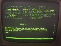
SUCCESS !! SMOKE FREE !!

My Compupro is back in business !! First of all, desoldering caps on an S-100 board with solder
wick was an epic fail. I don't recommend it. Since I was struggling, I opted to only replace the
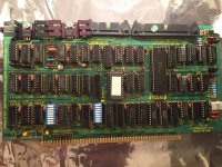
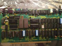
caps on the +18v and -18v unregulated DC lines on the boards that had failed, namely the SS1 and DISK1.

I've included pictures of those boards. The new caps are yellow ones in the upper left corner of
the SS1 board, C4 and C8. Those caps had smoked and charred. I replaced them with tantulum 6.8 uf
35v. The other two caps replaced are in the lower left corner of the DISK1 board, C15 and C17. C17
had shorted to 0 ohms but looked normal. I replaced those with tantulum 1.5 uf 35v. I managed to
read the 1.5 uf value on the old caps since they weren't burned.

The only other board I'm nervous about is the Interfacer 4. It has caps clearly marked 20v on
those same supply lines. Like I said previously, my DC lines are running 20v !!! From what I've
read online the recommended voltage rating on tanulum is twice the operating voltage, hence 35v.

BTW - the symptom I get when the fuse is blown for the +18v is that when reset is pressed, the
floppy head loads and the select light stays on. The head will seek to track 0 but no load
activity is heard from the floppy drive.

Thanks for the good advice, next time I'll follow it :)

Larry G

success.jpgDISK1 new caps.jpgss1 new caps.jpg
 
Back
Top