• Please review our updated Terms and Rules here

Swtpc ct-82

falter

Veteran Member
Joined
Jan 22, 2011
Messages
6,573
Location
Vancouver, BC
I bought this sad sack today:

http://www.ebay.ca/itm/vintage-SWTP...250184?hash=item3ab6e03548:g:VQAAAOSwkZhWTQ0c

My overconfidence is legendary -- I know I'll never find the keytops for it but I'm thinking I might be able to replicate them. The circuitry? No problem! Hah!

I think I overpaid a bit on this one, however, there were two reasons I went for it.. well, three really: 1) It's SWTPC, 2) I've always thought these terminals were really cool looking and 3) It's in Canada already. No border hassles, taxes or USPS/UPS extortion. Finding really good vintage stuff already in Canada is rare. Really rare. I passed on a 6800 system a couple years ago up in Canada and have been kicking myself since (still looking for a 6800 if anyone has a line on an affordable one).

Wonder what you guys think of the screen garbage and what I'm likely in for trying to fix it. I'm content with it as a static piece if it must be.. it just has that really way out vintage look I seek out.
 
Hard to tell what's on screen from that picture but from the looks of the mashed keyboard, maybe that's generating massive keystrokes
 
I havn't looked at the CCTS for the CT82 but if its the similar to other screens random characters at power on is the normal state of things. The RAM contains garbage, something then clears it. However the vertical bars on the display show something else is wrong. Probably not the character generator as I think most characters look OK. Pretty sure its fixable. PSU voltages would be the first place to start...

As for the keys some one else has been moulding key tops using the sort of stuff they use for casting things like Chess Sets. Not cheap but doable. I wonder if a nice solution would be to 3D print the legend and then rey and use that to make a 2-part casting?
 
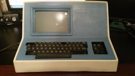
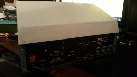
Got the CT-82 today! Wow.. it's much smaller than the pictures suggest. Only maybe 25-30% bigger than an Apple II.

20151211_175548.jpg 20151211_175601.jpg

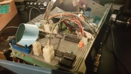
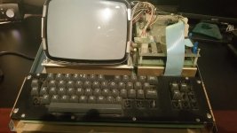
The thing I love about this unit is it has that SWTPC semi-amateur feel to it. The plastic top is pretty flimsy and the insides are very basic. Kind of feels like something a hobbyist would assemble with spare bits of metal.

20151211_175701.jpg 20151211_175637.jpg

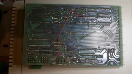
Here's one of the two detachable cards:

20151211_180224.jpg
 
Last edited:
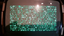
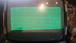
And finally a couple screenshots of the screen when it's on. I adjusted the brightness and the lines are gone. I then began playing with the DIP switch inside, which SWTPC provided to set different modes, like half or full duplex, conversational mode, etc. Some settings produce the garbled screen seen in the second pic.

20151211_183252.jpg 20151211_192504.jpg

Also the block about 8 or 9 chars from the left is actually a blinking cursor.

But there is no life -- the system does not respond to keyboard commands to clear lines, or anything. I'm thinking maybe a memory fault? No idea where to go on this one. :)
 
what is it attached to? Do you have an SWTPc 6800? The garbled characters indicate "nothing" to show. Do you have the manuals/docs?
 
It wasn't connected to anything. I am still waiting on a 6800 to come up on ebay but no luck. But I did download the manual from swtpc.com and supposedly with certain settings you can put it in a mode where you can just type whatever, nothing connected, for testing purposes. But I get zero from keyboard input. I don't think the screen is supposed to fill with garbage either.
 
No, no proper schematic. Still reading through the (very detailed) manual.

Dumb question -- according to the manual, this unit was supplied with either 2114 rams or 4045-30L -- the two aren't compatible are they? I'm strongly suspecting I've got some bad RAM here, and I have tons of spare 2114s.. but I'm assuming 4045s are different. Wondering what they would be compatible with in case I have something.
 
From the data sheets I have found - yes, the two RAM types are compatible.

Just make sure they are TMS4045 and not CD4045! One is a RAM the other is a CMOS counter...

I'll have another look tomorrow for the schematic.

Dave
 
From the data sheets I have found - yes, the two RAM types are compatible.

Just make sure they are TMS4045 and not CD4045! One is a RAM the other is a CMOS counter...

I'll have another look tomorrow for the schematic.

Dave

Okay well that theory is now out the window.. I piggybacked some 2114s, and it *does* eliminate that bizarre second screen pic I had there.. but still otherwise frozen characters.

I thought I might pull the 6802 chip and see what happens, with it out, no graphics at all. Thought I might try swapping it but all I have loose are 6809s. I do have a 6800 in my ASCI system.. not sure if the 6802 is compatible with that.
 
I don't think the pinouts of the two are compatible.

The 6800 requires an external clock - whilst I think the 6802 has an onboard clock.

Pins that I think are different between the two are: 3, 35, 36, 37, 38 and 39.

We need to track down the schematic... Anyone else help with the whereabouts of the schematic?

Dave
 
Made a discovery. The problem here really feels like a ROM problem. It reminds me a lot of the behaviour of my PET before I fixed the 6540s. Reading the documentation it appears the control rom was seated in the socket set aside for an optional rom. When I moved the rom to the IC1 socket and set to program mode, I now get a blank screen and brief beep on startup. Nothing appears on screeb typing though..
 
Well that's good news - this seems to indicate that the processor is working (the beep) and it can talk to the video board (the cleared screen).

I would proceed by setting the DIP switch to those identified in section 2.1 of the manual on page 2-1. These settings should cause a loopback within the 6802 software itself and not require the RS232 buffers and external connection.

If that works - we can work out why the RS232 buffers and/or interconnection doesn't work. If that doesn't work - we need to work out why.

Have you measured all of the regulated power supply voltages (especially the +/- 12V required of the RS232 interface chips)?

Dave
 
On second examination, I believe the manual is in error. On this site there are a few shots of CT-82 terminals, including one I believe is mine. A working one is there also with the proper boot screen (just a cursor to the top left), and inside it's ROM chip is also seated in what the manual calls the optional ROM position. Somebody goofed, I think.

http://terminals.classiccmp.org/wiki/index.php/File:SWTPC_CT-82_201238309868-6.jpg

So back to square one again. If the ROM is hooped, there's probably no way to get this thing running again as I've not seen many of these terminals out there and finding a replacement ROM might be impossible.

Well that's good news - this seems to indicate that the processor is working (the beep) and it can talk to the video board (the cleared screen).

I would proceed by setting the DIP switch to those identified in section 2.1 of the manual on page 2-1. These settings should cause a loopback within the 6802 software itself and not require the RS232 buffers and external connection.

If that works - we can work out why the RS232 buffers and/or interconnection doesn't work. If that doesn't work - we need to work out why.

Have you measured all of the regulated power supply voltages (especially the +/- 12V required of the RS232 interface chips)?

Dave
 
Eureka!

I decided to remove socketed chips one by one to see what affect they had. I pulled the INS8250N chip and voila! Blinking cursor! Then set the DIP switches and switched to programmable mode, BINGO.. we have liftoff!

View attachment 28309

According to the manual the affected chip has something to do with communications. I'm hoping it won't be hard to find. There's still no output or input between this and my computer so I'm assuming that chip is vital for that somehow. The chip was also inserted backwards (at least, if the socket guide was to be believed). Anyway, a live CT-82.. just needs this chip and then we can see how much of the serial communications system is still alive!
 
Well done that man...

The INS8250 ***IS*** the parallel to serial converter (UART) for use with the serial port. No UART - no serial comms.

There are plenty of recycled INS8250 'pulls' being sold by a recovery company in the UK at http://www.apache-electronics.com/stockall.php.

I would now try setting the DIP switches as identified in section 2.1 of the manual on page 2-1. These settings may bypass the UART altogether.

Incidentally, how are the links configured on the 6802 board? 16/32 (this must match the size of ROM), CLK INT/EXT (this should be internal), DIR (as per manual) and A/B ON/OFF (manual states OFF).

Incidentally, I get an error when trying to view the attachment for your last post ("Invalid Attachment specified. If you followed a valid link, please notify the administrator"). Erik?

Dave
 
Looks like we're not completely out of the woods yet. The machine operates ok but every so many power ups it goes wonky. I'll type in A and get something else. And the video is kind of wavy. Seems to happen most when I put the cover back on. Weird.
 
I am a bit confused by your last post.

When the machine is operating - is it OK (i.e. no wavy screen and what you type on the keyboard echoes on the screen correctly)?

Does it only exhibit these problems "when it goes wonky"?

You could have a problem with old capacitors, dry solder joints or dirty chip legs/sockets.

It could be temperature dependent (case on = lower ventilation). Try warming everything in turn with a hairdryer and getting a can of freezer spray and go around each IC until you find one / more that either cause a problem - fix the problem when you put some heat in or take some away.

Dave
 
Back
Top