• Please review our updated Terms and Rules here

PET 2001-8 Alive!

falter

Veteran Member
Joined
Jan 22, 2011
Messages
6,573
Location
Vancouver, BC
After many weeks, my repair guy came through and followed the schematic to get my Chiclet PET working again for the first time since I've owned it. It's not quite perfect -- the brightness control for some reason doesn't work. There is also a light green wire I noticed when I got home that is loose and not connected to anything. Because the brightness control doesn't work, the brightness is maxed with retrace visible. If anyone has any ideas how I might dial it down, or what that green wire is for, that'd be awesome.

Otherwise, it's pretty cool to see this thing that has been inop for 13 years (ever since I got it, basically) actually working today.

Now I have him replacing caps on my CT1024 terminal!
 
Noticed something with the monitor coming on at full brightness.. if I leave it turned off for a while.. each time I do it will power up at normal brightness for longer and longer each time. The third time I was able to enter a short program before the retrace began to show.. and only in the middle of the screen instead of all over.
 
I'd recommend recapping the Analog board for the monitor. There might be a few oddball values but I know that between Lees and Main you can get the caps locally like I did when my DEC VR201 was doing the same.
 
I think we did that. And they put a new brightness control on, but it doesn't seem to do anything. And there is this mystery green wire off the CRT neck that isn't connected to anything.. thinking that might be involved somewhere. Some of the docs I've read mention it relates to brightness somehow.

The fellow that did this for me doesn't speak English terribly well (eastern European).. it was hard to understand but it sounded like he had to do some fancy footwork to get it going again.
 
Looking at a schematic, the green wire goes to the control grid G1 of the CRT tube and to the wiper of the brightness control. With that wire disconnected, the symptom will be extreme brightness with retrace lines. The wire should go to a point labeled G1 on the circuit board.

Larry G
 
I doubt it. It's usually stranded wire and probably got torqued putting it together, working when he tested it but the final strands broke loose while transporting it, etc. I was in the repair business - been there, done that ...

Larry G
 
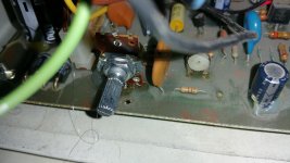
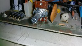
Wish I'd taken a picture of how it was before. There are two holes in front of the brightness control.. one has a bit of solder in it and some bits of copper wire. Wondering if that's where it needs to be.

1452985284557.jpg

1452985366431.jpg
 
Ok.. so no risk of things blowing up here if I connect to that little eyehole on the top of the brightness control? :) Always nervous with CRTs. Strange that they didn't reconnect it. No evidence of solder there.. I'm assuming they cut it from the other one. Wish I had a picture of the monitor as it was before so I'd feel more confident.. hehe
 
I borrow from this post:

http://www.vintage-computer.com/vcforum/attachment.php?attachmentid=19698&d=1406995123

It shows a shot of his monitor insides.. with the green wire soldered just to the right of that little resistor. Looking in mine, sure enough, there is a hole there with some solder and broken wire pieces.

I'm guessing there is a difference in design here between the original wiper and this replacement one they've installed. I just want to be sure before I connect anything that I'm not going to blow the CRT (or myself) up. :)
 
Last edited:
Do you have a voltmeter? You could measure that point on the board while you turn the brightness control. It will vary from 0 to -45V or so. If so, just needs to be soldered back in.
I'm sure it just broke off accidentally from replacing the control.

PS - I see I missed some posts and photos. If that lug hole on top of the control varies 0 to minus 45V can just solder there if easier. BTW - there might be voltage on the metal shaft so turn with a screwdriver, not fingers.

Larry G
 
Last edited:
Turned out to be the hole on the other side of the resistor. Soon as I connected the wire to it, brightness control worked again. So we have a normal PET 2001. Yay!

Almost. I'm wondering if anyone has a good (safe) procedure for making the keyboard work better. Mine is fairly ok.. all keys work, but some require tons of pressure to get anything out of them. Not looking to make a bad situation worse.

Also, the tape deck in this thing -- I can rewind to the beginning of a tape, do a load command and it'll find the first program on there.. but then as more tape is pulled over from one side to the other, it stops. If I hit stop and then play again, it'll play again for a little bit and then slowly stop. Guessing weak motor.. not sure what if any rehab procedure there is there.

Thanks for all your help guys. I've waited a very long time to see this thing do.. anything really. :)
 
It does seem a little weak.

Another separate Q.. I'm using one of my external cassettes to try loading some PET programs. These are Commodore approved tapes that work in other PETs I have and that claim on the label to work with 8k PETs. Many of the programs though produce an undefd statement error.. I'm assuming thats a limitation of the early BASIC version and not anything wrong with the PET itself. It does seem to work with some programs.
 
As far as the tape drive goes, if that is a standard cassette tape player then FF to the end and REW the tape to loosen it up. Also the capstan drive would have a rubber pinch roller that might need to be re-vitalized by cleaning, etc.

Larry G
 
Back
Top