• Please review our updated Terms and Rules here

MPI BR8A8 Stepper Buzz

NeXT

Veteran Member
Joined
Oct 22, 2008
Messages
8,133
Location
Kamloops, BC, Canada
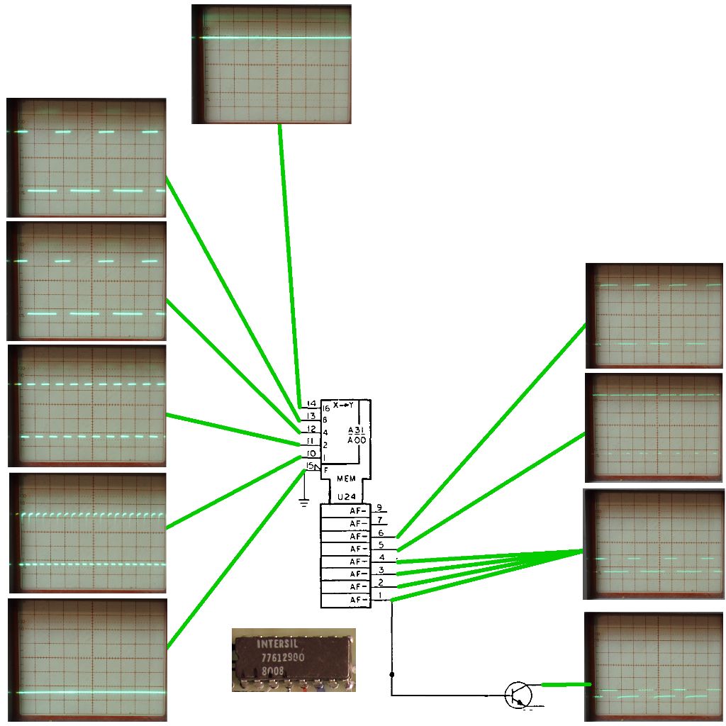
I have an HP enclosure with two of these 8" floppy drives in it. Both seem to pass the floppy controller's tests but one drive in particular seems to constantly buzz the stepper motor. Unplugging everything but power to the drive verifies it's something on the drive itself but before I dive into the schematics if I can find them I'm curious if anyone else has run across this issue before.

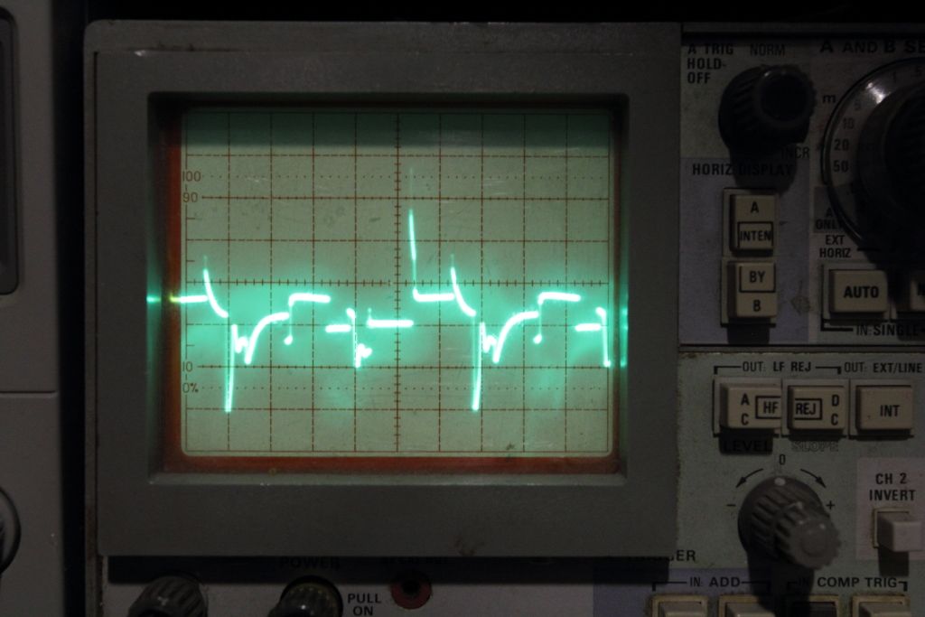
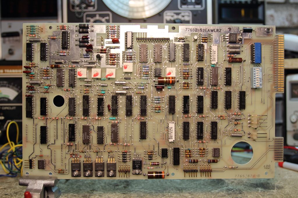
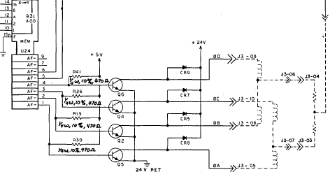
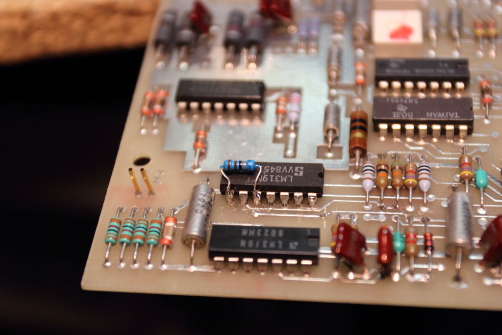
Edited: I'm checking the voltages for the stepper and there's no DC voltage flowing when the buzzing is happening however I am getting up to a 3v AC voltage. The thing is, if I unplug the AC for the spindle motor it persists until I disconnect the DC power for the logic, so the AC is being created somehow from the DC source. I pulled the four TIP120's that seemingly drive the stepper and they all checked fine on my transistor tester. Also checked the four diodes between them and the pin header, plus the TIP125 right next to it. That all tested good as well.
 
Last edited:
Alright, test jig is setup as so:

-Two matching floppy drives (one seemingly good, the other one is this malfunctioning one)
-One PSU powering both
-Drive controller disconnected

Stepper coil (any winding will do) to base on TIP120 (any of the four). Scope voltage set to 5v.

IMG_2308.jpg


On the working drive this should be a flat line. (0v)
^^^ NEVERMIND THAT. I WASN'T REFERENCING GROUND^^^

In any of the TIP120's from Base to Collector. Scope voltage set to 1v:

IMG_2312.jpg


Again, on the working drive this should be 0v.

While doing this the buzzing has now become the drive retracting the heads until it rattles against the back stop so I've had to completely unplug the stepper to continue testing or else I'll rattle the heads out of it.

I've gone over the listed CDC floppy drives at bitsavers but I can't seem to find this drive or its schematic.
 
Last edited:
So is this more abnormal than just lack of a home sensor ? My 8" drive is pretty noisy retracting to home position on power-up.

Larry G
 
Without the controller attached the drives don't home themselves. They should just sit there spinning their spindle motor and my functioning drive does exactly that.

Edited: I saw the PDF for the 9406 already. It's really close to this drive but the PCB layout is different and the test points aren't where they should be.
 
Just looking at that schematic as a guide. There are several small electrolytics in the control logic to the stepper motor. You could scope for AC waveform on each cap + and - leads with respect to ground. They should have identical waveforms.
Or just try jumping them with a close enough value cap. Does it look like it's performing a smooth stepping out travel or just random motions ?
 
Actually now that you recommend it as a guide I learned I was not properly referencing my scope to ground so that totally alien waveform was incorrect and should be disregarded.

The other waveform however seems to be a recurring pattern around the driver logic so far. There's in most places I've poked a 5V rise and fall which I can only assume is what is causing the stepping. IT is not present on the good drive and the oscillation I can only assume is what was giving me that AC voltage reading.
 
For reference, here's my board:

IMG_2316.jpg


The stepper motor is driven by the row of four TIP120's on the bottom left. They all seem to get their signals through a chip marked "Intersil 77612900" I can't tell if the faulty signal is being injected ehre or spit out through all the outputs so long as I don't have a proper datasheet or pinout. It is also ridiculously drawn in a way I've never seen before.

intsl.png


From there onwards the traces scatter about and trying to figure out what everything does from a schematic and component layout NOT for this board is frustrating the hell out of me.
 
I would still snoop around those silver electrolytic cans in the mid-left area with your scope comparing AC waveforms on each end of them looking for differences.
An open one could induce AC which could inject a false stepper signal as you say. Those SMD's inside glass cases like in the right center are also capacitors.
 
The voltage rails have no ripple and all those smaller caps are simply for decoupling. I have no way to test them and the signal I'm seeing is far too clean to be AC ripple.
Give me a few minutes to plot out what I'm seeing.

Edited:

wafeforms.jpg

Save for pin 15 and pin 14, none of the signals match up to what is observed on the same chip on the working drive. I should be seeing 1-5 low, 6 high, 10-13 low. No square waves. Something has to be generating it.
 
Last edited:
Quick glance, two lines running into U24 is a two bit binary word decoded to 4 state output to coils. A31 like a 4 bit counter. Why is pin 10 waveform rounded?
 
Discussing the problem with a friend it seems the POR reset bus is not firing when it should be. Should be low when idling but it's stuck high. As a result the drive just steps away uncontrollably. Still investigating.

For anyone curious, I've photographed the front and back of the board, dropped them and aligned them in GIMP and saved it as a multi-layer image. If you want to take a look for yourself you can click this link (20mb file warning). I have another version twice the size. Would anyone be interested in keeping a copy? Bitsavers?
 
Last edited:
I think we've got it.

IMG_2371.jpg


There's an LM319N dual comparator that isn't pulling its output low when it should be. At best it drops a volt but that's not enough.
The local shop does not have any in stock so it might be a few weeks until the new one comes in and we can verify it is just the chip.
 
Last edited:
This is weird.

So I've been able to confirm that the 319N is healthy. What is NOT healthy however is the input to pin 10. In a good floppy drive it should be 2v but on this drive it's 5v. Something is obviously pulling the voltage up but that's the thing. There's only three components attached to pin 10.

pin10.png


Three components. A resistor, a diode and a capacitor. The diode and capacitor have been replaced and the resistor measures within tolerance. There's no signs of shorting between traces. I even replaced the 319N to verify something wasn't pulling the input down. I'm stumped.
 
Last edited:
Ugh, son of a bitch.
So to pull the voltage down to where it should be on the drive (remember it was 5V, not the 2.1v that the other and working drive was showing) I added a resistor as a pulldown. This seems to of stopped the buzzing and quieted down all the logic.

IMG_2643.jpg


However now that we're ready to test if this actually fixes it, something else has gone bust.
Initially the 9895A enclosure both drives came in had the bad drive electrically disconnected. Even in that state the controller could pass a selftest, zero the heads and do a seek test. Now with either drive nothing happens.
It's a good thing that HP puts five status LED's on the front of the controller for easy troubleshooting. Too bad HP ****ing doesn't say in the service manual what any of the LED patterns mean. Instead they give a table for status codes seen on a diagnostic board I do not own.

I'll make a new thread for that.
 
Last edited:
Reading the manual I posted,
That is a power on reset latch. The RC network to pin 10 provides a delayed 5V high. At power on, pin 7 is high until C6 charges and overcomes the Vref on pin 9 then pin 7 is brought low permanently for not reset state.
I think your added resistor is holding it in reset, if I'm looking at the right circuit. Pin 10 should be 5V and not 2 volts. Maybe mis-read on the good drive? What is the voltage on pin 9? I'm guessing it would be like 2 or 3 volts.

Larry G
 
For what it's worth, the symbols that you see are IEC/IEEE ones. They've been a standard for a long time. CDC drew all of its circuit diagrams in this way, and many other manufacturers also do. The "distinctive shape" symbols for logic gates derive from a much older MIL standard.

You're Canadian/Canadien--you should be used to this.

Where I'd start is by drawing a complete circuit. It could well be that you have an open trace somewhere and are simply picking up stray AC hum.
 
I can try to explain what I think is happening, but I might not use the right technical names. The drive does not actively get track number information from reading the disk. At power on, it resets to track zero, and when it gets a command to move the head/s to a specific track, it pulses the stepper motor the correct number of steps from track 00. The stepper motor moves by powering different combinations of the stepper motor windings. If the motor does not step, or has a bad step, when the computer tells it to, the drive is still going to assume that the drive has stepped the correct number of times and the heads are positioned in the right place.

When a drive tries to step past track 00 to the outside or track 76 on the inside, there a good chance that the track 00 sensor is defective, OR the stepper motor drive is defective.

Sometime the logic that controls the stepper power develops a fault, and a bad/conflicting combination is powered on the logic board, and the stepper motor can't step. In these cases it may buzz. The computer and the drive will not be able to tell that the drive did not step to the correct track unless a request to read or wrote cannot be filled. From the outside, it may look like the drive is working, because the drive is going to assume that the heads are positioned correctly, and read or write at that location. As long as the drive can duplicate the motion each time it gets a command, there's no way to tell that it's on the wrong track.

Can you operate the drives outside of the case? If so, try formatting a disk, and watch to see if the heads are moving the same amount each times all the way from track 00 to track 76. Do the same thing on both the drive that is working, and the drive that is buzzing. If the head/s on the buzzing drive do not move smoothly and completely from the outside track to the inside, then there is a logic problem. Sometime the defect will only show up when stepping 1-2 tracks at a time. The problem is not always the transistors (or driver ICs), much of the time it's the logic that powers the driver transistors/ICs that is faulty.

When you have a step logic failure, the easiest way to find the problem is to set up a working drive next to the malfunctioning drive, and step both drives one track at a time, tracing the signal levels from the stepper motors back, comparing the transistors/driver ICs and logic to find the stuck or dead input or output with a logic probe or scope. I have the logic board schematics for the drives I've worked on marked with the signal levels of working boards to make finding the problem/s easier to find.
 
Without looking at the circuit diagram, sounds like Retrogear may have it right.

The one thing that I've learned from working on floppy drive logic boards is the input or output from a single chip can affect many functions on the logic board. One bad chip may fix the board, be the start of replacing a progression of chips before the board is fixed. I install sockets when I replace a chip to make future troubleshooting and replacements/repairs easier.

Have you tried monitoring the control output signals at the 50-pin edgecard connector and comparing the "good" drive to the "bad" drive? I'm pretty sure you're going to find that dragging that voltage down on that chip resulted in the drive logic board outputting/signalling not ready to the controller board.
 
MicrocomputerSolutions said:

Forget it.
I was going to make a nice writeup but his post was so incredibly ignorant I don't even want to work on this project anymore. I'll go back to using my 9885M.

Can you operate the drives outside of the case? If so, try formatting a disk, and watch to see if the heads are moving the same amount each times all the way from track 00 to track 76.
Like, what the hell is this?? Did you read anything in this thread? I'm done.
 
Back
Top