• Please review our updated Terms and Rules here

Paper tape readers x 2. PLease help.

Probably expensive. No probs with getting rid of one, in exchange for a few beer tokens. I actually have two good ones, I think , one dodgy one that sometimes punches but doesn't read. I also have 2 x GNT reader punches, several 5-level readers.
 
OK. I had an attempt at plugging the siemens in last night. Carefully constructed a cable from the mains with three ribbon pins attached to live neutral earth. I know the bottom pin is earth and went with the right pin being live as it connects with fuse. neutral to left pin. Plugged in, switched on and..... C10 on the main board burst into flames!! Tantalum bead. You can see it in the image as the black bunrnt thing next to the others. So what did I do wrong? Wrong live/neutral polarity perhaps... or faulty components on the power supply PCB.. not tested what voltage the transformer was putting out. :( As for the PTA612's... do you have a postcode? Assuming the unit weighs 17 kilos at an estimate, I could get a quote. Be happy to give you some beer tokens and a few magic beans.?DSC00418.jpg
 
Unless the PSU is strapped for 110V and you put 230v on it I don't think you have done anything wrong, except perhaps not to ramp up the mains slowly using a Variac. Tantalum capacitors do fail, see the threads on failed PC/XT motherboards.
 
Paper tape readers

Paper tape readers

Hi, my, those Plessey connectors are a silly price, I throw them away. Do a good, clear, well lit photo of the two connectors and I will see if I have any. What is important to be clear is the positioning of the large locating slot in the connector with the closest pin, one orientation is for mains connectors, others are for different uses. Just done a trailer full of scrap to the scrappy so might have all gone.

Still have several Trend 612 ( I think, away from home at the moment) 300 baud reader punches. These work, bit sluggish at times so have to spray IPA over the punch to clean the sticky oil off. Have some basic info on these punches, they were part of the Clansman system.
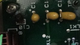
 
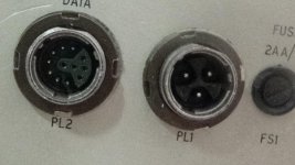
Hi Woodchips. OK, ive taken a picture of the two sockets. One PL1 is the mains and the other the data connector which looks like there is a split between reader and punch terminals..?? mebbe??.
What I've done since the blow out is found a 240V AC primary transformer that gives out 15V AC with centre tap and 13 V with centre tap. I've replaced the dead cap with another and am going to connect 15 0 15 to the AC connector of the power board....DSC00422.jpg
 
Last edited:
Thanks, will have a look but will take few days, away from home at the moment.
 
Put in a new cap.... blew again! this time using my external transformer however, even with the blown cap, the power light comes on and when I press the FEED or the BS button (what does BS stand for?) the motor spins. The green light on the reader comes on. So I think its a problem with the power distribution going to the main board..
 
Update: I think I've fixed the capacitor problem. It appears I might have put tin the new tantalum the wrong way round. Now when I turn the machine on (via my external transformer) it doesn't blow. I get readings of 5V on the chips.
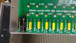
Now, I noticed there is a burned out component on one of the boards that looks like it could've been an inductor (the component is labelled L1 on the silkscreen so I'm assuming it was an inductor. I've put in a new inductor and when I press the "Reader On" button I hear a very high pitched whine coming from the punch/reader area of the machine... what could it be? (i'll post some pics of the board a bit later, right now I'm having dinner..)
 
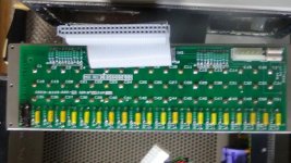
OK Here's a picture of the board. Its labelled "Filter board" on the other side. The burned out L1 (which I think was an inductor- worked it out. inductor 10uH....) is shown as well. DSC00434.jpgDSC00439.jpg

I've now worked out the squealing was coming from not having the same value as all the other inductors on the board and as its a filter... well yeah. :rolleyes:
 
Last edited:
paper tape reverse engineering-data socket

paper tape reverse engineering-data socket

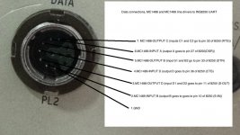
Now I've just spent a couple of hours reverse engineering the data socket to see where the connections go.. The machine uses mc1488 and mc1489 line drivers for the data in/out and an INS8250 UART.
I've done a pinout diagram with pin connections to line drivers and line drivers to the uart. Now, how would I talk to this thing??
dataconns.jpg
 
Last edited:
Found a three pin socket, I thought it was the wrong pin to alignment groove but looking at the photo looks correct.

If you still want it, might be incorrect, then PM me your address. Might be able to dismantle the connector to shift the alignment, can't remember, can't undo the fixing ring either.
 
OK thanks Woodchips! If its not a problem that would be great. (I'll PM my address) At the moment I'm powering the machine off an external transformer (13.5 0 13.5 AC). If I have the socket I can adapt the machine and not have to change the mains supply socket. I had a problem with the reader last night. There is a switch on the panel that selects between 5,6 and 8 pin read. The switch is mechanical and operates via a system of spring pins and a wheel with indentations... The pins had fallen out but I now know how it works so can put it back together. Have you seen the diagram of the data connector? I'm thinking of taking the plessey off and putting on a 9 pin D socket.. but how the hell do I communicate with it? I'm astonished at how little info there is on this model anywhere!!
 
Pin wiring to RS232 to USB converter...

Pin wiring to RS232 to USB converter...

Hi all. OK, I now believe I can get the machine to do something but I'm not sure how. I've done some tests on the data port pins using my oscilloscope and it looks ok. I was thinking of using my windows laptop and SIMH to talk to it. Or just attempting something simpler by wiring up the pinout (shown above to a 9 pin serial to usb cable (like the one here: http://www.ebay.co.uk/itm/NEW-USB-2-0-TO-RS232-SERIAL-DB9-9-PIN-CONVERTER-PC-ADAPTER-CABLE-GPS-PDA-UK-/351555289045?hash=item51da53ffd5:g:Ei4AAOSw~gRV1aXD and using Hyperterminal or Teraterm or one of the other serial monitors I have..

However, I'm not sure how the wiring would go so I'm asking for some help. Does anyone know the pinout from the machine to the cable? I'm assuming Rx goes to Tx and vice versa but what about the other signals? (RTS, CTS, DTR, DSR). As always any help appreciated and thanks so much for all the help already.
 
Well its usual to cross connect RTS(Request to send) -> CTS (Clear to Send)

For simple circuits this may be enough. Some others require full modem signals....

So as both sides are "DTE" (data terminal equipment) as opposed to a DCE (Data Communications Equipment or MODEM) they may also expect to see "Carrier Detect" and "Data Set Ready" being made active. We can drive these from "Data Terminal Ready" so cross connect:-

DTR (data Terminal Ready) -> DSR (Data set Ready) and (CD) Carrier Detect

This article may also help...

https://en.wikipedia.org/wiki/Null_modem
 
Hi Dave. OK, thanks for the info.

Well its usual to cross connect RTS(Request to send) -> CTS (Clear to Send)

Ok so you're saying RTS from the computer to the machine or vice versa? Also, the same with DTR to DSR and DCD.. Computer -> Machine or Machine -> Computer?

I've managed to get it punching using just the GND and Rx->Tx and Tx -> Rx.
I'm using YAT terminal and it is set to 300 Baud, 5 bits no parity 2 stop bits and no flow control.
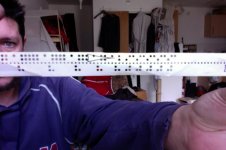
This is what I get when I send it the3 letters a repeated 4 times and numbers 1 to 5...
Photo on 06-03-2016 at 14.29.jpg

No luck with the reader yet though. The Step button doesn't seem to do anything and I don't think its sending. I think there might be a cable connected incorrectly. I'll post some pics in a bit.
 
Back
Top