• Please review our updated Terms and Rules here

My *Third* CT-1024 Terminal

falter

Veteran Member
Joined
Jan 22, 2011
Messages
6,573
Location
Vancouver, BC
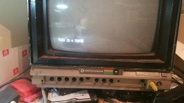
Had the great fortune to run into a fellow on one of my yahoogroups feeds. The discussion was about my TVT project boards and he mentioned he might have something he built back in the day. Turns out he had a CT1024 terminal, built completely by himself in 1977 (he even etched his own PCBs from the plans). He offered it to me for a very (very) reasonable sum and today here it is.

20160410_092532.jpg

It's housed in a very solid aluminum sheet casing he built. I'm not sure whose keyboard that is (haven't taken it apart yet). He also eschewed the P197 power supply my other units have (a smart call, I think).

20160410_092524.jpg 20160410_092528.jpg 20160410_092532.jpg

Neither myself nor the former owner know what this board is for exactly:

20160410_092544.jpg

It's not an upper/lowercase switcher. It mounts directly to the memory board. I'm wondering if maybe it increases the lines to more than 32 characters.. it appears I have 64 characters across for each line.

20160410_092549.jpg 20160410_092559.jpg
 
Last edited:
Here's the back side:

20160410_094137.jpg 20160410_094133.jpg

I don't recognize the cursor control board. I assume it's a SWTPC design given the 'COMPUTER CURSOR' script on the back, but I haven't found it on Michael Holley's site just yet.

20160410_093841.jpg 20160410_093849.jpg
 
I had to temporarily get around the BNC connectors on the back and had a few glitches getting it going (serial card was 1 pin too far to the left). I had a garbled picture initially but this unit has a sync dial on the back. I don't think my other, complete CT1024 has that, unless that's the third trimmer on the motherboard (can't remember offhand what the third one does). This unit just has two trimmers on the board. Anyway, turning the dial I got my random character picture. Woohoo!

20160410_100228.jpg

This is the screen I *should* be getting on my other unit. Instead the best it does is a field of ? marks, which is what it normally would do with the cursor control, memory and serial boards out. So perhaps that tells me something is wrong there -- beyond the power supply issue, which is still being worked out.

The cursor control board on this machine seems to work though. On my other CT1024, functions like EOL and EOF appear to be attached to dedicated buttons or switches. On this unit, CTRL key sequences are used. All of the sequences work, except for cursor up and cursor down. In my imagination, the cursor control meant I could move the cursor freely all over the screen. I cannot do that here.. in fact, I cannot carriage return to get a new line.. Return simply puts the cursor back at the start of the line. There is a New Line key, but the only effect that has is if your cursor is at the start of the line -- it will clear whatever is on that line.

CTRL-S and CTRL-Q I *think* switch pages of memory. If I type a line and hit CTRL-S, what I typed goes up a line and I can type below. If I hit CTRL-S again, nothing.. but if I hit CTRL-Q and then CTRL-S alternately, it switches lines back and forth, so I can edit one or the other at a time. I'm thinking this must be the memory page switching function? I tested it and put TEST 1 on one line, CTRL-S, then TEST 2 on the next, then CTRL-Q.. it put TEST 2 at the top of the screen and I could edit TEST 1.. if I hit CTRL-S again it switches them and so on.

20160410_094324.jpg

I'm not sure what the switches along the top of the keyboard do. The second one from the left appears to make the cursor do a really high speed blink. I think that was a feature. Another I think toggles local echo.. but no idea what the others do yet. Unfortunately the original owner doesn't have his notes anymore. Oh well, still grateful he provided this to me. At last of the three I have a working (I think) TVT2!

With regard to the serial board, it appears that there are just a few loose wires. The owner mentioned he had built an acoustic coupler modem out of tin cans and I guess had it hooked up to those somehow rather than a DB25. There is one DB25 on the unit but it's for the keyboard.
 

Attachments

  • 20160410_092624.jpg
    20160410_092624.jpg
    92.9 KB · Views: 1
Opened the keyboard and found the labelling for all but one of the switches up top. Woohoo!

No luck figuring out how to use 'all' of the screen available to me, or if it's even possible. I may have misunderstood how a 'TV Typewriter' works, but I'd thought you could put text pretty much anywhere on the screen. The keyboard has a hand written legend that notes different cursor controls. They all work except up and down, which is curious. I looked around for anything that might be astray -- broken wires, missing chips. I did notice on the 'mod' board that is fastened to the RAM board that there was one unfilled IC socket. I don't know exactly how this board, which I think is used to generate 64 characters per line, relates to the cursor board, but I can see some wires between them. Anyway, looking around it seemed like much of the rest of the board was 7400s, so I took a stab and put a 7400 in. Machine behaves exactly as before. I've tried all the carriage return key combos SWTPC has in their manuals to no avail. More reasearch I guess! :)
 
On my TVT, I rigged up a few gates on a bit of perfboard to handle incoming character-to-cursor/screen control. I also modified mine to display a single screen of 64 character lines, instead of two pages of 32. Both modifications were fairly trivial. To the best of my recollection, the original only decodes CR and LF codes--but you can leverage more decoding off that circuitry.

I couldn't have been the only one to do this.
 
I discovered on inspection that two pins for the serial card had broken off during shipping (found piece of one on the motherboard). The fellow that built this used fairly thin copper pins that aren't quite as strong as the ones used by SWTPC. I kind of jury-rigged a contact using some thick wire I had.. and now the key sequence to move cursor down blanks a line rather than doing nothing. Have to check again to make sure they are making good contacts.
 
Found my problem. I consulted photos the previous owner had taken before shipping and found one connector in the wrong place on that add on card that's on the front of the memory card. Soon as I put it to the correct place, the normal CR and LF functions worked, and I could go up and down. The operation is a bit different than what I was expecting. I thought you'd have basically one complete page on the screen to play with, and could move the cursor all around the screen to edit on any line you wanted, similar to a word processor. However, what it actually does is the cursor stays at the bottom and when you do a line up, it simply brings a line down to it, or vice versa if you go down.

The CR process is a bit different too.. rather than simply hitting return and getting a new line, you have to hit Return, then Line Feed.

I'm just glad it's working now.. at least, the TVT part of it. The next trick will be seeing if this serial board is alive. Which will be a more difficult task since the outputs for RS232 (I assume that's what it uses) aren't labelled. Any ideas on how to trace those Chuck? I've got about 6 loose wires that could be the TX and RX.
 
The CR process is a bit different too.. rather than simply hitting return and getting a new line, you have to hit Return, then Line Feed.

You've lived too long with computers--and not long enough with real terminals. That's exactly the way a terminal should work. I did have an old Beehive terminal that could also use 1F hex (ASCII US) as a newline character.

On old TTYs, the sequence to start a new line was CR LF RO RO. RO = rubout. The two rubouts are there to allow time for the mechanism to complete the action.

Yeah, the only working terminals I had before were my CT-82, but that does seem to allow you to do whatever you want with positioning the cursor. It's quite a bit different from this one.

I'm hopeful now I can finally isolate my issue with my original CT1024. The power supply on this one having screw terminals tempts me to try connecting it to that one to see if it rids us of our video problems. We replaced the caps and the white fuzz is gone but it's still distorting/twisting the video at top and bottom.
 
I'll have a look again when I get it back. I'm thinking because the custom built PSU in my working CT1024 has screw terminals I might just patch it into the old one to eliminate power as a suspect. I forget -- PLLs are ICs right? Usually 8 pin? I'll look it up.

Also I'm trying to test out the serial capabilities, if any. I'm somewhat blind because I don't know what parity, baud, etc settings it's on right now. But IIRC from our previous conversation, I could just take the TX and RX wire and join them, then switch off local echo and type to see if anything comes back, right? I believe I have the right wires.. the connector he has is a 16 pin IC connector rather than the molex the original has, but the traces on the card appear to be the same so I'm following those. One time when I had my CT82 hooked up to it and switched the CT82 off the CT1024 beeped.
 
The PLL in the CT1024 is more a circuit than an IC, if memory serves, and may involve the lowly NE555--this is all from the haze of 40 years, so I'm not very solid on this guess.
 
Looking by the trimmer that handles the sync -- there is indeed two NE555s down there. On my working CT, he has his own trimmer wired up to the back of the unit rather than a little trimmer pot on top. I'm pretty sure I played with that trimmer before without any success, so maybe it's time to get the board out and check out the 555s.
 
Okay it appears the serial connection works. I found I had one of the wires wrong.. once I connected it, set the terminal receiver on, and switched off echo.. it worked just fine. Wow.. pretty amazing that this thing still works after all this time.
 
What's more surprising to me, coming from the other end is that it's pretty trivial to put a terminal, complete with UART and character generator in a small MCU that costs less than $5 today.

OTOH, I'm still wondering what to do when a telephone menu instructs me to press "1" when I've answered the call from a rotary dial phone.
 
Looking for help on this one. I've got the Ct1024 hooked up to a laptop and they do communicate, however every now and again there are strange characters that appear, or if you type above a certain speed it loses things (maybe I type faster than 1200baud?).

I'm limited somewhat by the fact that I don't yet know what setting on the baud dial is what. I cranked it all the way backwards in one direction and started at 110.. that is where I get some action. However, I'm not sure how to translate this from the manual:

ODD parity NO bit 8 jumper J to K and jumper I to H and jumper G to F
EVEN parity NO bit 8 jumper I to H and jumper G to F
NO parity NO bit 8 jumper I to H
NO parity bit 8 = l NO jumpers
NO parity bit 8 = 0 jumper E to D

According to the serial card jumpering, I have 'EVEN PARITY NO bit 8' with I to H and G to F jumpered on this serial card. Does that mean on the PC side I set the terminal to 7 bits, even parity, 1 stop bit (options are 1, 1.5 or 2)? Am I understanding that right? And I'm assuming flow control is none?
 
A lot of stuff understands 8 bits, no parity with bit 7 = 0. That's the way I set mine (according to my notes)--E to D. The board maxes out at 1200 bps. The "stop bit" really isn't a real bit (how could you have half a bit?), but rather the "dead time" between characters. So setting 2 stop bits will space the characters out some if you have problems with framing errors. Otherwise, 1 stop bit should be fine.

You can get more detail data from the UART datasheet, but it's hard to find; the AMI S1883 was already old by the time the TVT came out. In my kit, SWTPC substituted the GI AY-5-1013A which is plug-compatible with the S1883 and for which, there is plenty of documentation.
 
Hi All;

Chuck, "" OTOH, I'm still wondering what to do when a telephone menu instructs me to press "1" when I've answered the call from a rotary dial phone. ""
I thought I was the only one with that kind of a problem.. I have a Radio Shack 'Pocket Tone Dialer' that I never use, just in case.. Cat #43-145, if this is of any help..
I do though have a touch tone phone hooked up to my Switchboard, for when I am going to call a place that I need touch tone accessibility..
And I think I could put the call on hold and switch it from the Dial phone to the Touch Tone Phone, but, I have not (I think) ever done this..

THANK YOU Marty
 
What's more surprising to me, coming from the other end is that it's pretty trivial to put a terminal, complete with UART and character generator in a small MCU that costs less than $5 today.

OTOH, I'm still wondering what to do when a telephone menu instructs me to press "1" when I've answered the call from a rotary dial phone.

Sing. I saw a documentary one time on a guy who could sing DTMF.
 
It'd have to be sing and whistle, wouldn't it? Aside from Tuvan throat singling, I didn't think a human could do DTMF. Mostly, my dial phones are in the shop and garage, so it isn't too much of a problem to put the phone down and go to a different room. Both have been around a loooong time--one a Trimline and the other a 500 series wall phone. You just can't kill the things.

At any rate, @falter, if you have the facility, check the baud clock for your CT1024--as I recall, they were none too accurate. It should clock at 16x the bitrate. That'd be the UART pin 17, which, at 1200 bps, should read 19.2KHz. Any significant error can produce some bizarre results.
 
Back
Top