• Please review our updated Terms and Rules here

6850 ACIA interface troubles

Now that I've done some more testing (and gotten it hooked up to a proper terminal) I'm looking into the slow transmission issue. If I type fast I can also get it to mess up receiving, but I don't know what'd cause an ACIA to run fine, but very slow. The baudrate gen. must be fine, since it transmits the characters correctly.
I'm still suspecting the E line, since that's the main enable for the chip, and is used to clock everything in it, it seems from the datasheet. using a 3x faster crystal, it should be clocked a lot more frequently, thus cycle the ACIA more often, but I'm not sure that's the right thing to look at for a problem.

It could be a timing issue with the E clocking. Perhaps inserting some equal amount of spare NAND gates as a delay would do some good.
If we assume it's a software thing (when I force-outputted, no delay), it must run in the check transmit data register empty loop. Data can only be entered on the negative edge of E pulsing. Could be there's a timing mismatch but it sync's up every 10 or 100 or so loop cycles, giving the delay.

[The delay is considerably smaller now that I'm running a NEC D8085AHC-2 at 4 MHz, oddly, it was the processor change and not the clock doing the big difference.]
Could also be the R/W being too fast - it's latched in the altair8800 cpu board.


Could a handshaking problem cause dead slow but correct operation?

-On a separate note, I used the memory examine/entry routine to test out the RAM, it works fine.
 
Last edited:
You said you are generating E from (RD- nand WR-)? That doesn't sound quite right to me, but it has been a long time since I used either an ACIA or an 8085. I looked at the schematics but didn't see the ACIA. You need E to be high whenever you are trying to read from or write to the ACIA registers. I noticed your code uses I/O instructions rather than memory access to get to the chip. Is your E guaranteed to be in the correct state and transition at the right times? Check the bus timing diagram on page 4 of the ACIA data sheet. Note in the timing diagram the address and R/W signals are held after the end of E.

Do you have a scope or logic analyzer? How many signals can you watch at once? I would suspect the relationship between E and the chip select and the R/W- line, and maybe even the data setup and hold timing.
 
E is edge triggered, so it clocks on a rising/falling edge, as far as I could read. The /read and /write NAND'ing is the scheme used in both the original altair 2-SIO card and the turnkey card, so I'm fairly sure that's the way to go (not 100, though). Only difference is they have more gates inbetween, so it could need some delay, perhaps.

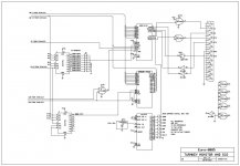
The acia is on a schematic on page 1 in this thread, sorry, should have added that. here:TURKEY-1REV1.4.jpg

Only one channel works on my scope, unfortunately. I do have a logic analyzer, but I don't have the probe so it's a bit of work to set up. In theory, I could then monitor 48 channels at once. I just might have to do that. I think you're right in it might be a E/RW/CS thing.

Yeah, I see what you mean. R/W should shift just after E goes low, but when E is generated from the /RD and /WR signals, that isn't likely.
I'm using S1 as a R/W signal, maybe I should delay that with a couple of inverters?
 
Last edited:
Yeah, I see what you mean. R/W should shift just after E goes low, but when E is generated from the /RD and /WR signals, that isn't likely.
I'm using S1 as a R/W signal, maybe I should delay that with a couple of inverters?

I don't remember the 8085 cycle details well enough anymore to be sure if just a delay will do the trick. Also, keep in mind that the address, chip select and R/W- signals must be set up well before E goes high (numbers 13 and 14 in the bus timing diagram), and they all, plus write data if a write cycle, must be held beyond E going low (numbers 9, 15, and 21)..
 
Last edited:
You may be right. But it's a small thing, lifting a pin on some chips and make a quick and dirty delay to test it out.
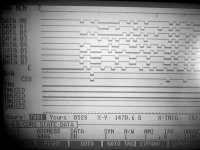
I've made a cable for my logic analyzer (soldered directly to a spare 6850), here's some timing:
Unfortunately, it's not as detailed as I'd hoped, as I don't have a better probe than that.

IMG_0689.jpg

I've enhanced it a bit for it to look more dramatic :p
No really, tried to squeeze it for some contrast. late 80's lcd displays were crap.
 
I've made a cable for my logic analyzer (soldered directly to a spare 6850), here's some timing:
I am assuming that CS2- is the only chip select you are actually using. You will notice that E is not dropping at the end of the pictured write cycle to the ACIA.
 
Yes, exactly, and cs2 is of course active low.

You're right, but I don't get then, how every single 8080/8085-->6850 design uses similar decoding with success.

Could I NOR it with the /CS? So that when /CS goes high, it goes low?

Anyway, look at this altair compatible computer:
http://mini-altair.tripod.com/Mini-Altair.pdf

It uses a microcontroller to punch BASIC into a giant RAM chip, but look at the ACIA logic. The only thing I'm doing different, timing-wise, is not having the chain of gates between S1 and R/W. The other inputs to those gates is just an inhibit and ability for the microcontroller to use the ACIA, I think.

Another thing- how fast DID the original turnkey monitor operate?
I've gotten it up to about 5 char's per second.
 
Last edited:
You're right, but I don't get then, how every single 8080/8085-->6850 design uses similar decoding with success.
I don't know. Have you tried duplicating all of their logic and see what it looks like? There are a few more terms in there, and they are using all of the chip select lines. There may also be less well documented ways to run the bus cycle effectively that do not depend so much on E. I wonder if there is an application note, or a hobbyist article about that.

Could I NOR it with the /CS? So that when /CS goes high, it goes low?
Maybe. But my money is on getting E to transition at the right time. Also, if you look at the data sheet it says you need a transition at least every 9.5 microseconds (so I assume the part is at least partly dynamic).

Another thing- how fast DID the original turnkey monitor operate?
I've gotten it up to about 5 char's per second.
No idea, but I used ACIAs in the early '80s with 6800 family micros and they ran at the baud rate (interrupt driven) with no troubles. But in that case E is trivially easy.
 
Last edited:
Looking in the 6800 application manual and it only specifically says the 6800 is dynamic, but the data sheet for the 6850 gives a maximum E period of 25us, is that dynamic? The E signal clocks the interrupt logic, so must also affect the status port flags.
 
Looking in the 6800 application manual and it only specifically says the 6800 is dynamic, but the data sheet for the 6850 gives a maximum E period of 25us, is that dynamic? The E signal clocks the interrupt logic, so must also affect the status port flags.

What I see in the sheet I linked above is 10 us max cycle time for E, 9500 ns (i.e. 9.5 us ) for E high width, or 9500 ns for E low width, with a maximum rise and fall time of 25 ns. An earlier or later data sheet might show something different. Of course, they don't tell you what will/might happen if you exceed those values.
 
Could I NOR it with the /CS? So that when /CS goes high, it goes low?
Maybe. But my money is on getting E to transition at the right time. Also, if you look at the data sheet it says you need a transition at least every 9.5 microseconds (so I assume the part is at least partly dynamic)
.

Tried gating the E line with /CS. That killed it completely, so you're right, that's not really the solution. I agree, can't see it being anything other than a timing issue.
Maybe E should be timed to S1 and S0. They can be used as /WR and /RD respectively, but they're stable from the start of the cycle (sais the 8085 datasheet).
Furthermore, they're both 1 during opcode fetch cycles and on reset, inhibiting E from clocking at those points.

The thing with E timing I don't get is even when I delayed it by several ttl gates, it didn't seem to make a huge speed difference, if any.
It stands to reason, that if a timing error causes it to work slow, it must be because the timing catches up every now and then, and doing anything timing-wise should offset that.
 
Using s0 and s1 for E generation is a bad idea. The whole idea of using s1 for R/W is that it's enabled before E...

Also tried bypassing the CS logic, to see if it selected the chip too late, didn't impact the speed in the slightest.
 
Last edited:
Last edited:
Back
Top