• Please review our updated Terms and Rules here

HP 9845B Workstation and a lot of Extras

Did you post an earlier message about that? I didn't see it. Is that an HP 264x terminal? I have a pile of those. I'll have to have a go at cleaning out the CRT goo on some of mine.

-Glen

My message doesn't read right on second look, I was commenting on the cleanup of this computer,then posted an example of my screen restoration, and yes that is a 2647, I have a extra key board looking for a screen if you have any to spare.
 
My message doesn't read right on second look, I was commenting on the cleanup of this computer,then posted an example of my screen restoration, and yes that is a 2647, I have a extra key board looking for a screen if you have any to spare.

I have more 264x terminals than keyboards. Almost all of them have screen rot now that needs to be cleaned up. I'll have to take a look at exactly what I have. Do you ever get down towards the Seattle area? They are probably not cheap to ship.
 
If I counted correctly, I currently have the following:
(2x) 2640B
(4x) 2645A
(6x) 2645A with dual CTU
(1x) 2647F with dual floppy (most interesting one, it runs BASIC locally)
13 terminals total and only 7 keyboards.

I haven't powered any of them on in a while. I think almost all of them powered up last time I tried. Some had more screen burn or weaker screens than others. Almost all of them have some degree of screen rot now and could use a good cleaning in general.

If you ever get down in the Seattle area you could have a 2645A and another for parts to go with your extra keyboard.
 
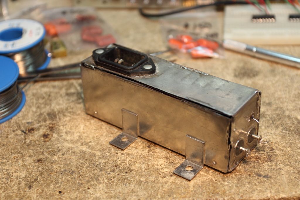
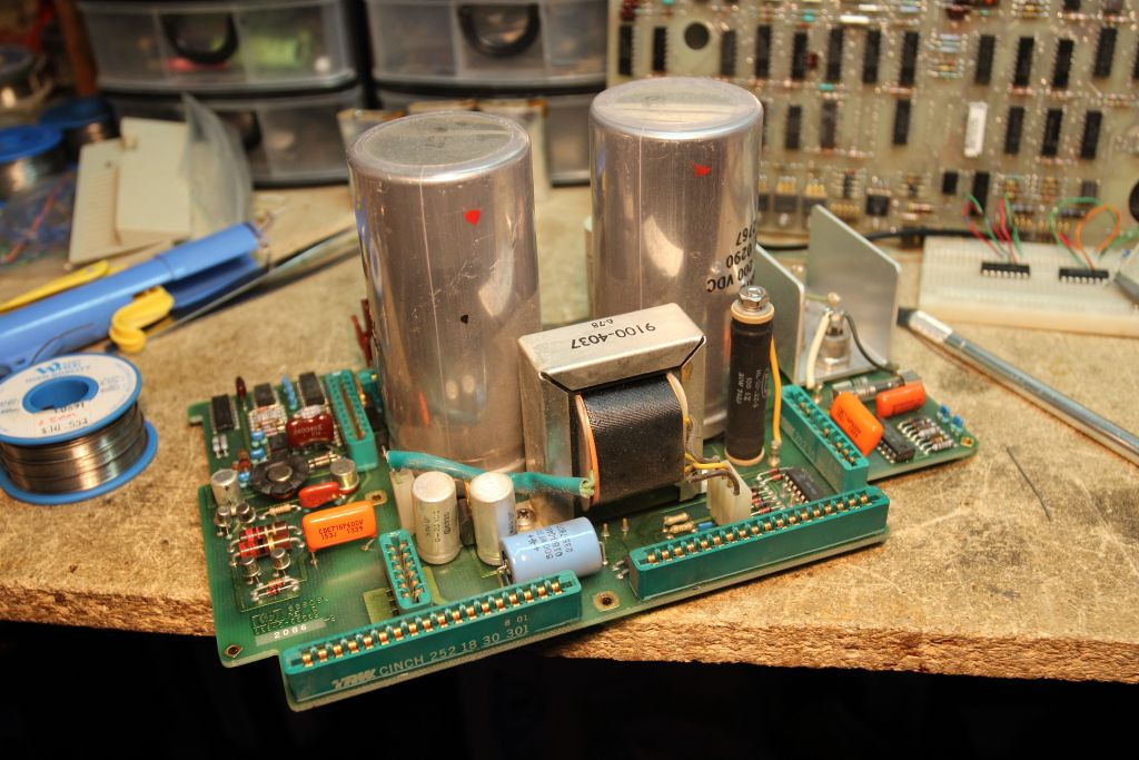
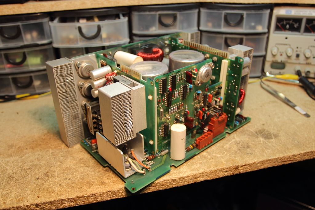
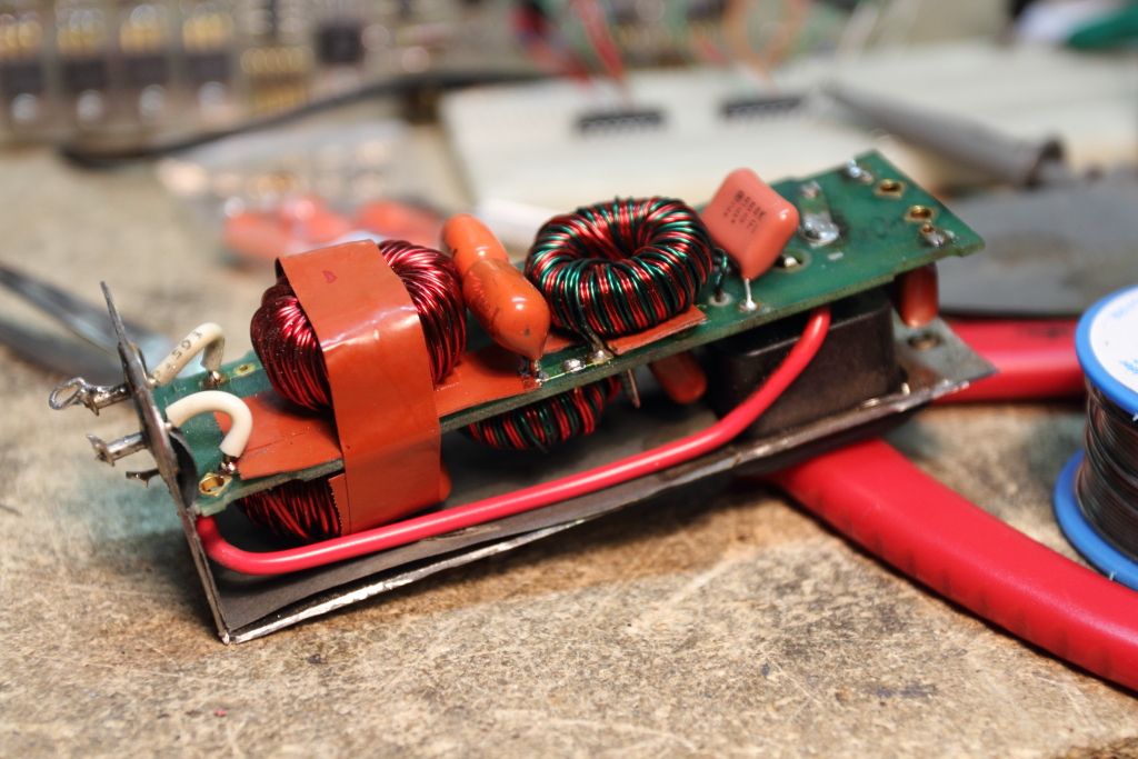
Recapping of the RIFA caps in the AC filter and the power supply have been completed. The metal can that houses the AC filter was tacked shut again using solder and the Weller gun.

IMG_2634.jpg

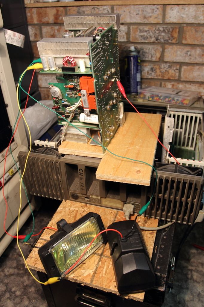
IMG_2636.jpg

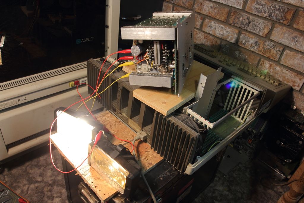
IMG_2638.jpg


Load testing and voltage rail health will be done this Tuesday hopefully.
 
I had a few loose ends clean up earlier than expected so I was able to load test tonight. The loads were to vehicle fog lamps. At 5v they have a 4A inrush load and a 1.5A nominal draw and at 12v they have a 3A inrush load with a 2.5A nominal draw. That should be enough.

Anyways, the power supply was setup as described for testing, the switch was flipped and....nothing. :/
+5, +12, +18, +17, +13....everything. Aside from the two 175V primary capacitors none of the voltages came up. Obvious thing to first inspect was the fuse and it's fine. Second obvious thing to check was if any of the transformer windings had gone open and they all seemed okay as well from an ohm's perspective. It has to be something really early on in the PSU circuit. It's as if nothing secondary is receiving power.
Well the schematics are available but I'm curious. What might be causing this? Any ideas?
 
Last edited:
I found the solution to the roller in the tape drive. Good ol' Terry's Rubber Rollers.

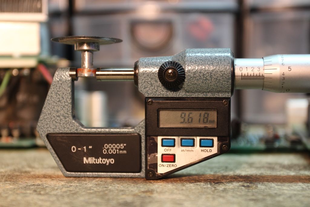
We exchanged a few emails and he determined that even with the strobe wheel attached he could apply new rubber at his base cost of $35 USD. The roller without rubber is 9.5mm, give or take 0.1mm. The addition of 0.5mm of new rubber brings that up to around a solid 10mm which should be fine.

roller_diam.jpg
 
Me and a buddy named Chryseus on another forum have been slowly going over the power supply. Against my recommendation he took the extra time to redraw the schematics for the main board of the PSU so they were actually readable now.

zD5QROj.png


My progress so far has determined that the LM340T-8 and -12 are good, replaced C13 and reported back on test results. We're currently looking over the +5P circuit which seems to power and reference some of the logic on the lower half of the diagram. Every transistor however I've checked in-circuit has seemingly tested good however and Q1 and Q2 are intact so we didn't have +180V make its way into place we don't want it.
 
Lots of poking around and testing was finding not much until U1 on the clean output board was tested. It's a -12v regulator but no matter how I wired it on the breadboard after a few volts the current draw took off so I'm suspecting it to be bad. I replacement will need to be sourced.
Edited: God dammit, readings are more accurate when the multimeter is properly cabled. The regulator is fine and the search continues...

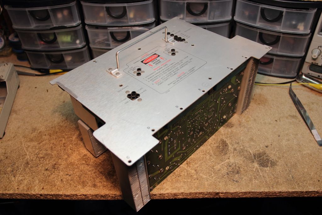
Edited: Just in case anyone was curious, here is the block that makes up the bulk of the first generation power supply. It receives the line input already converted to DC. From there the magic happens across five boards. (High Voltage, Low Voltage, Dirty Output, Clean Output and the Mother Board which everything plugs into) Poking at the outwards facing test points while assembled and a load added to +5 and +12 is an outright pain in the ass.

IMG_2794.jpg

IMG_2788.jpg

IMG_2786.jpg
 
Last edited:
Nice work on the schematics.

Watching with interest as I have 3 of these that need repairs when I can spare the time.

Dave
 
Right now the one big thing we have noticed is that it seems the +8v regulator is getting heavily overloaded for some reason.
With just +24 feeding it it has a nice +8 out. We add the low voltage board and the load goes up about 100ma but things are still good. We pull that and then plug in the high voltage board again we have a 100ma load but we're still good.
Now add both boards and the load goes up to 500ma and the regulator gets way hotter than it should be. It doesn't even have a heatsink.

Now add all the boards and now the load is so heavy (or at the point where it's nearly a full short) that the regulator is notching down the output to an unusable 3.7v We're trying to figure out why it does this.
 
Last edited:
The voltage on U7 is wrong when we we were checking the OC1 signal. What is happening is that the +8v is converted to +5 for PSU internal logic on the low voltage board which then drives this however because out +8 reg output is being heavily throttled to 3v or so there is simply no regulation going on and the logic voltage is far too low to work.

But why.....We've tested just about everything....
 
Things still do not add up. We power +8 externally and everything comes up in spec with a 500ma load which is 1/3 what the 8v regulator is rated for. We bypass +8 completely and add 5v externally after the second regulator that drops it to +5v and the load is still fine. Nothing is blowing up. Nothing is overheating....except the 8v regulator. The 8v regulator has to be faulty.

It's listed as 1826-0146 which is an LM340T-8. The 5v version is still cheaply available on ebay from china but the 8v version seems nonexistant. The variants are even worse as they can be found but the brokers are nuts. One guy has it for $6, plus $150 shipping.

http://www.unicornelex.com/7808T_8V_Positive_Voltage_Regulator_p/18-1370.htm
 
The 8v regulator has to be faulty.

It's listed as 1826-0146 which is an LM340T-8. The 5v version is still cheaply available on ebay from china but the 8v version seems nonexistant. The variants are even worse as they can be found but the brokers are nuts. One guy has it for $6, plus $150 shipping.

The LM7808 is the same, and costs about 50 cents.

Any of these should work fine: http://www.mouser.com/Semiconductor...z63xZ1z0wbz1&Rl=5cg9gZerbbZ1z0wd73Z1z0wbdjSGT

Dave
 
Yep. They are the same. I'm usually working out of some ANCIENT parts books so there's a lot of newer components not listed. I ordered a catalog from digikey twice now and they never sent it.
Anyways, I've ordered a half dozen off ebay and they should be off the boat sometime next month.
 
PROGRESS!

I was given a replacement power supply on loan. He had not tested it in a few years but indeed, it works.

IMG_3702.jpg


The plan for today is to swap the boards between my working machine and his non-working unit to verify that my fault is the regulator.

as for my new 7808 it seems of vanished int he mail, so I gotta order another package of them and wait another month....or call the local electronics guy and hope he at least has a damn 7808 in stock.
 
Last edited:
The fault is not the 8v regulator. All the boards are now tested and everything is healthy...except the low voltage regulation board.

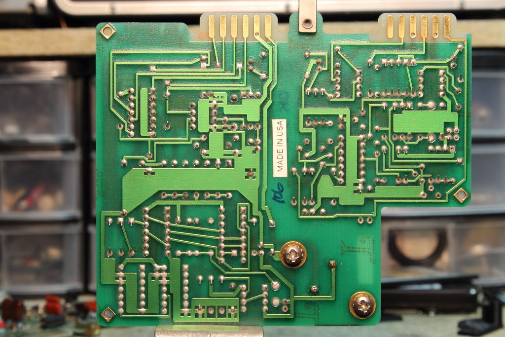
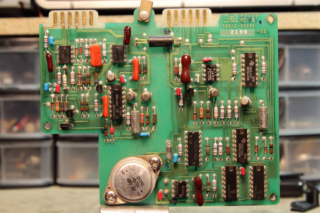
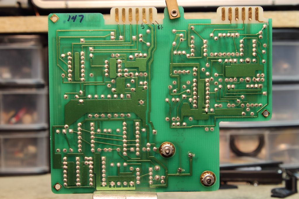
Both boards seem to have the same layout however the good board has several IC's omitted. Why exactly I do not know. The only know schematics for this board do not match, plus the layout diagram is for another diagram.

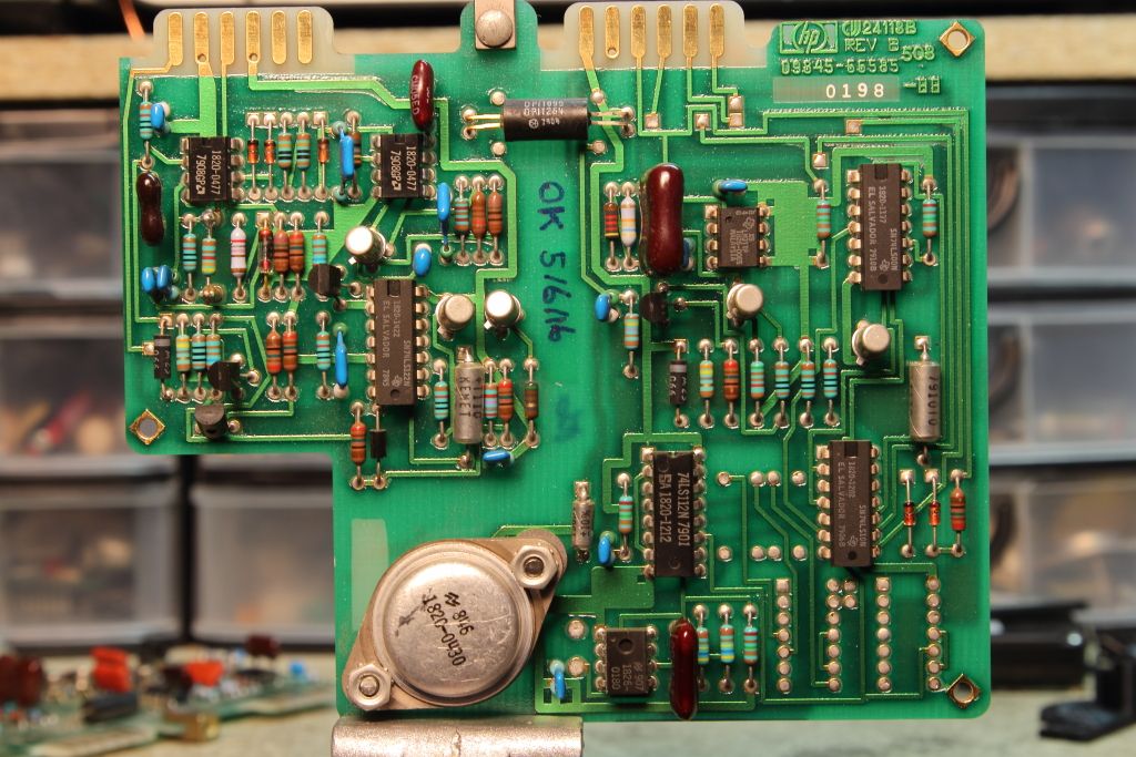
The good board:

CGS_1319.jpg

CGS_1320.jpg


My board (the bad board):

CGS_1321.jpg

CGS_1322.jpg


That large regulator take the +8v from the 7808 and converts it to +5v which is then passed around. When I fed it 8v directly from the bench it seemed fine but beyond that there wasn't much else I tested.
 
Alright, well I took a step forward, then a step back.

As I was troubleshooting the above board I put it back in for a test and powered up, there was a brief presence of a voltage on the +5 and +12. Progress. Turned it off and tried again. It did it again, for slightly longer. Did it again. A little longer. Did it again. Nothing.

I swapped back in the good LV regulator board and I had no output. After some more card shuffling it appears my formerly good clean output board was now totally dead. No voltages were present on it. There was also no volts present on the dirty output but when I swapped in a good clean output board its voltages came right up. Went over the now bad board and tested U1, Q3, Q5 and the five rectifier diodes. They all seemed to test okay both in and out of circuit. there's an additional eight diodes buried deep on the board and at least in circuit they tested fine (high reading one way, low reading the other). I really doubt I blew the transformer.
I also replaced the 8v regulator for the hell of it. :confused:

Good news is I found that a 10W 100 ohm resistor makes a great discharge tool for C17 and C18. No more waiting ten minutes before I can touch the thing.
 
Last edited:
Decided to tackle the LV board first, then I'll troubleshoot the clean output next. The clean output board isn't killing other boards. The LV board apparently is. :|

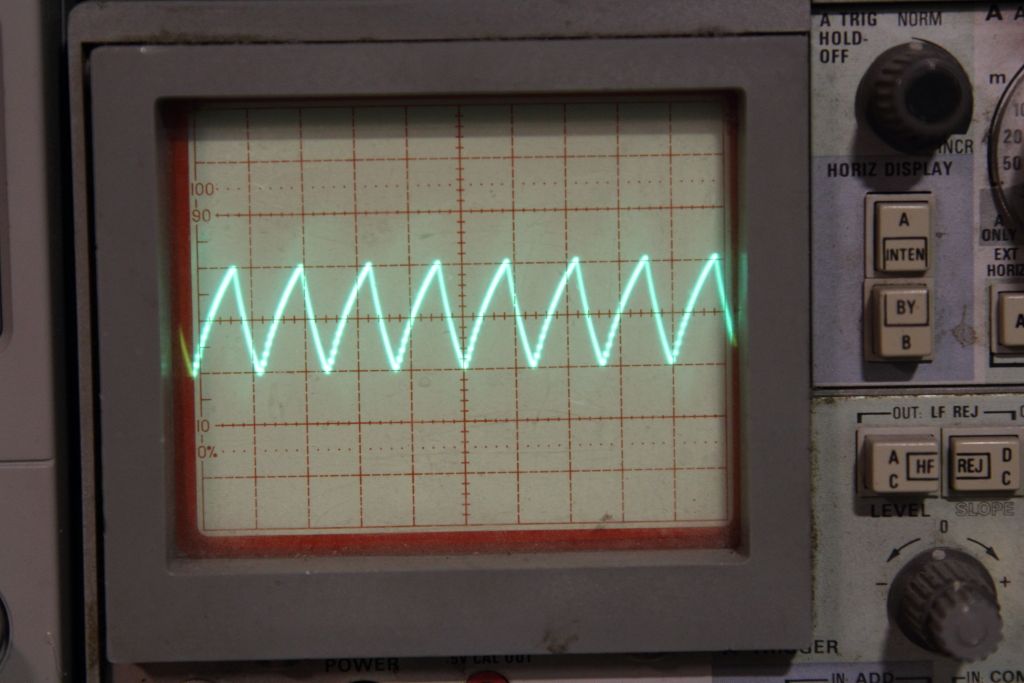
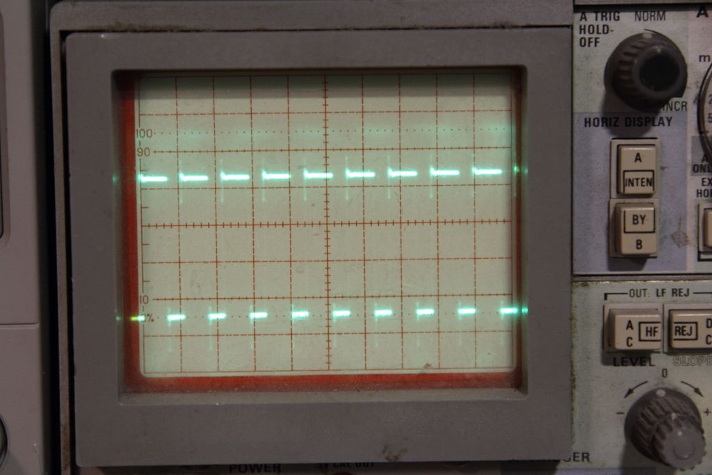
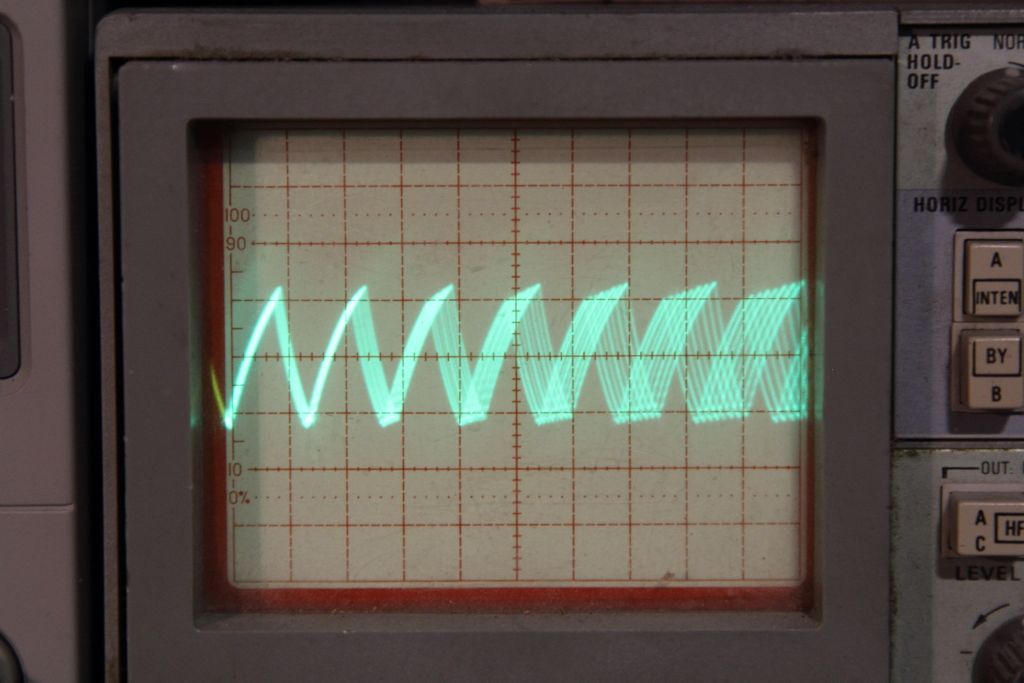
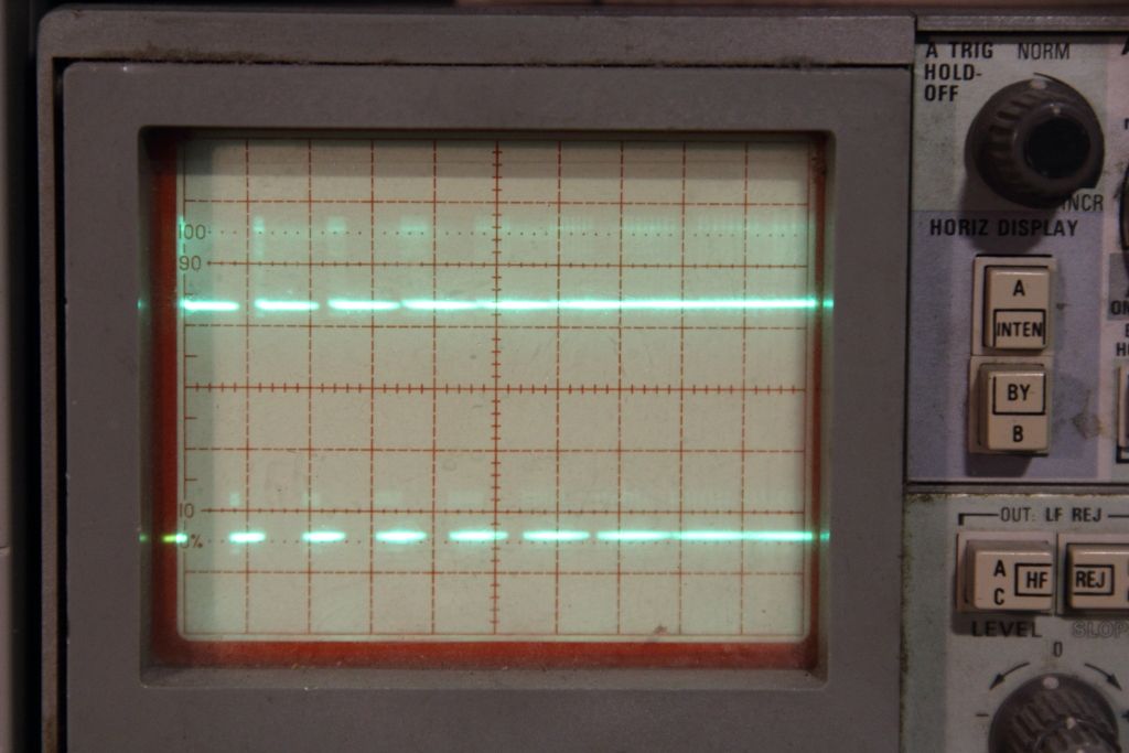
Powered the 5v regulator and began poking around. First I noticed that the signal pins on the 555 timer were ghosting.

Good board:
CGS_1324.jpg
CGS_1325.jpg


Bad board:
IMG_3713.jpg
CGS_1323.jpg


Replaced the 555 timer. no change. The distortion seems to be present all over the place.

Editline: On a suggestion I started pulling the IC's and watching to see if the problem vanished. The first I pulled was a Signetics made 74LS112N and once it was out the problem vanished from all over the board. OF course it's the Signetics.
I'll have to order a new one.

Edited:
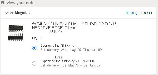
Oh man, these choices. Pay nothing and wait a month, or pay $25 and wait even longer.

shipping.png
 
Last edited:
Back
Top