ldkraemer
Veteran Member
That complete Row of keys is fed by A5 going "HIGH" making Z1 Pin 3 "HIGH" and Pin 4 "LOW". Notice PULLUP Resistors R1 thru R8 Pulling the D0 thru D7 Data Lines "HIGH".
When you Press a Key such as the 8 you make contact from A5 to D0 which pulls Z3 Pin 2 "LOW" making a "1" on D0.
8 = D0
9 = D1
: = D2
; = D3
, = D4
- = D5
. = D6
/ = D7
It should be easy enough to remove the Z80 CPU, Pull A5 High through a 4.7K Resistor and troubleshoot Z1 Pins 3 &4 along with Z3 Pins 2 & 3.
KYBD* will also have to be "LOW". The remaining Keys are just a continuation of Z3 & Z4 Pins for D1 thru D7. The remaining keys just
progress thru D1 to D7.
It should be easy to troubleshoot to the specific node of the IC. It could also be a bad Solder Joint, or a defective ribbon in that flimsy
keyboard cable. But, either way, it should be easy to locate.
If when you depress the 8 key you are getting the following keys @XHP instead of the 8, there is still a problem with the A0-A7 Address lines when it's
trying to access the keyboard.
Larry

When you Press a Key such as the 8 you make contact from A5 to D0 which pulls Z3 Pin 2 "LOW" making a "1" on D0.
8 = D0
9 = D1
: = D2
; = D3
, = D4
- = D5
. = D6
/ = D7
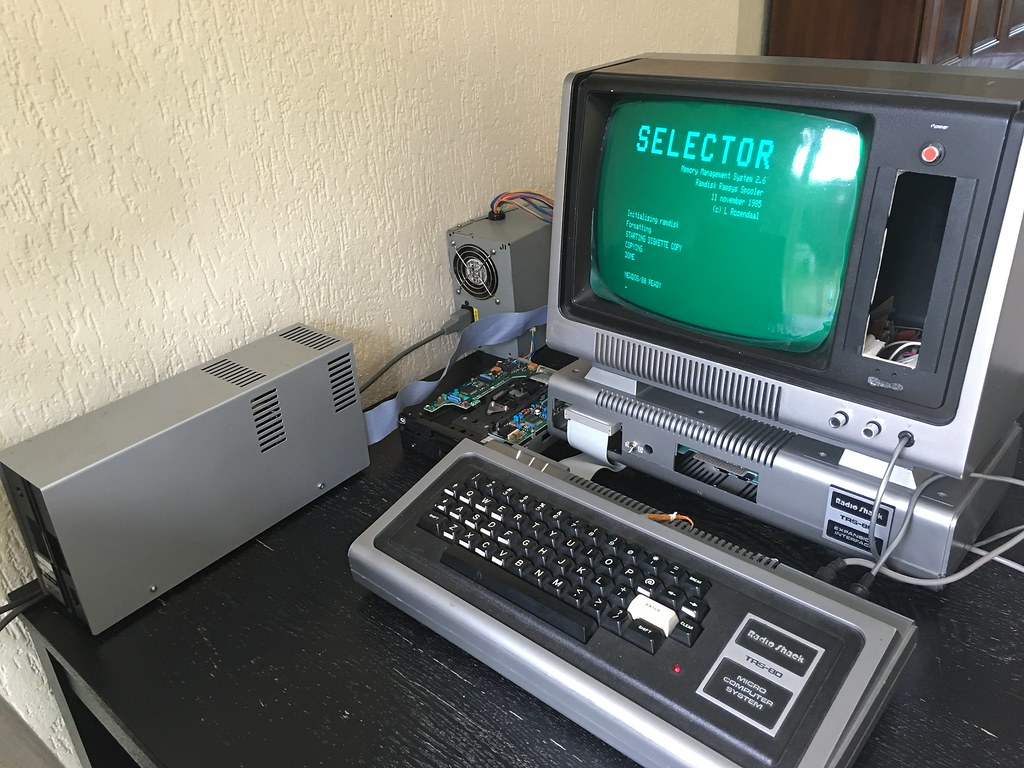
Keyboard
The TRS-8O Keyboard consists of 53 single-pole.
single-throw normally open keys molded in a
plastic base. The base is mounted, together with
four ICs and associated resistors, to the key-
board PCB. As you can see from the Schematic,
this Keyboard does not output ASCII. It is scan-
ned, like calculator-type keyboards. Each key
represents a switch across a matrix node. When
closed, the switch will short out a horizontal
line to a vertical line. ROM software will detect
the node short and generate ASCII equivalents
for that particular key.
The Keyboard is accessed by decoder signal
KYBD*. When this signal goes low, it enables
tristate buffss Z3 and Z4. The inputs to these
buffers are normally held high by the pull-up
resistors (at the top of the keyboard schematic)
R1 through R8. All of the horizontal address
lines are made to go high at the same time as
KYBD* goes low. If the CPU detects a logical
"1" on one of the data lines, there is a key
pressed on the Keyboard. The CPU ROM will
then scan the address lines one-by-one until it
finds the "1" output on the data bus again.
After finding it, the ROM can instruct the CPU
how to generate the ASCII code for that parti-
cular key. At this time, the CPU also checks the
status of the two shift keys. If neither of these
keys is pressed, the ASCII code is not modified,
If a shift key is pressed, the ASCII is modified
accordingly.
Only one point should be brought up about the
Keyboard. The inverters on the address lines are
open-collector types. You may not be able to
see the address signal on Z1 or Z2's output
unless one of the keys associated with that out-
put is pressed. With no key pressed, there is no
voltage applied to the KR (Keyboard Row)
lines. When a key is pressed, the associated pull-
up resistor supplies voltage. Then you will be
able to see activity on a KR line.
It should be easy enough to remove the Z80 CPU, Pull A5 High through a 4.7K Resistor and troubleshoot Z1 Pins 3 &4 along with Z3 Pins 2 & 3.
KYBD* will also have to be "LOW". The remaining Keys are just a continuation of Z3 & Z4 Pins for D1 thru D7. The remaining keys just
progress thru D1 to D7.
It should be easy to troubleshoot to the specific node of the IC. It could also be a bad Solder Joint, or a defective ribbon in that flimsy
keyboard cable. But, either way, it should be easy to locate.
If when you depress the 8 key you are getting the following keys @XHP instead of the 8, there is still a problem with the A0-A7 Address lines when it's
trying to access the keyboard.
Larry
Last edited:
")