• Please review our updated Terms and Rules here

Change CPU in a PDP-8A from KK8A -> KK8E

According to this document:
http://www.pdp8online.com/pdp8cgi/query_docs/view.pl?id=246
the DEC part number was 19-14194, "high ct" (high current?), if that's of any help. There are a pile of opto-isolators made in DIP-8 packages, and I don't know what recommends one over another.

According to the BA11-A_RevE engineering drawings on bitsavers, there was also another opto-isolator, a 19-23364 "hi isolation 8kv" in that device.

Vince

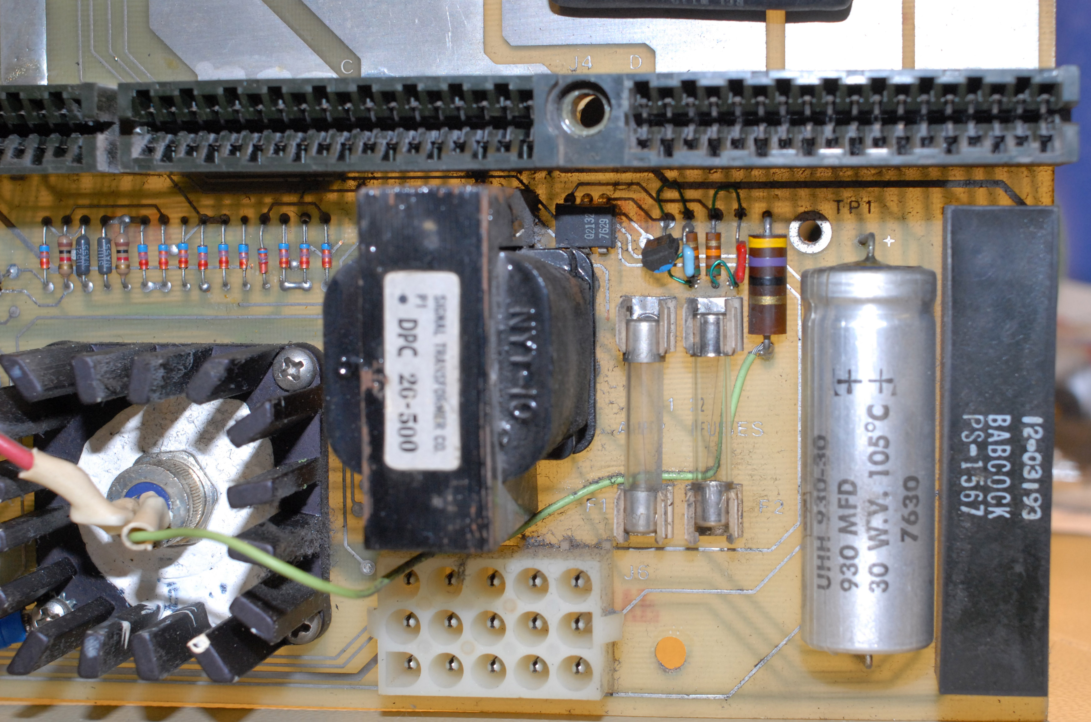
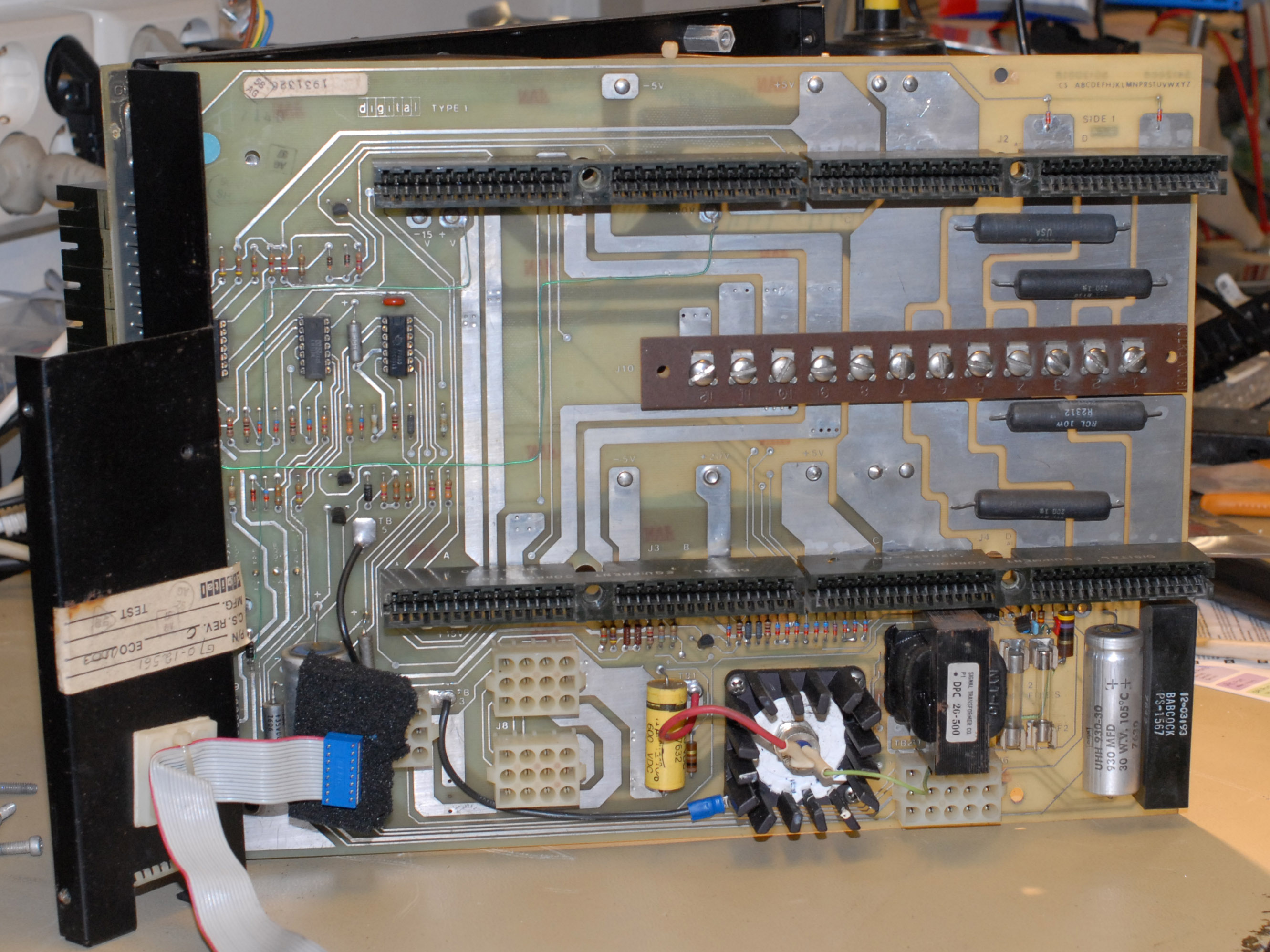
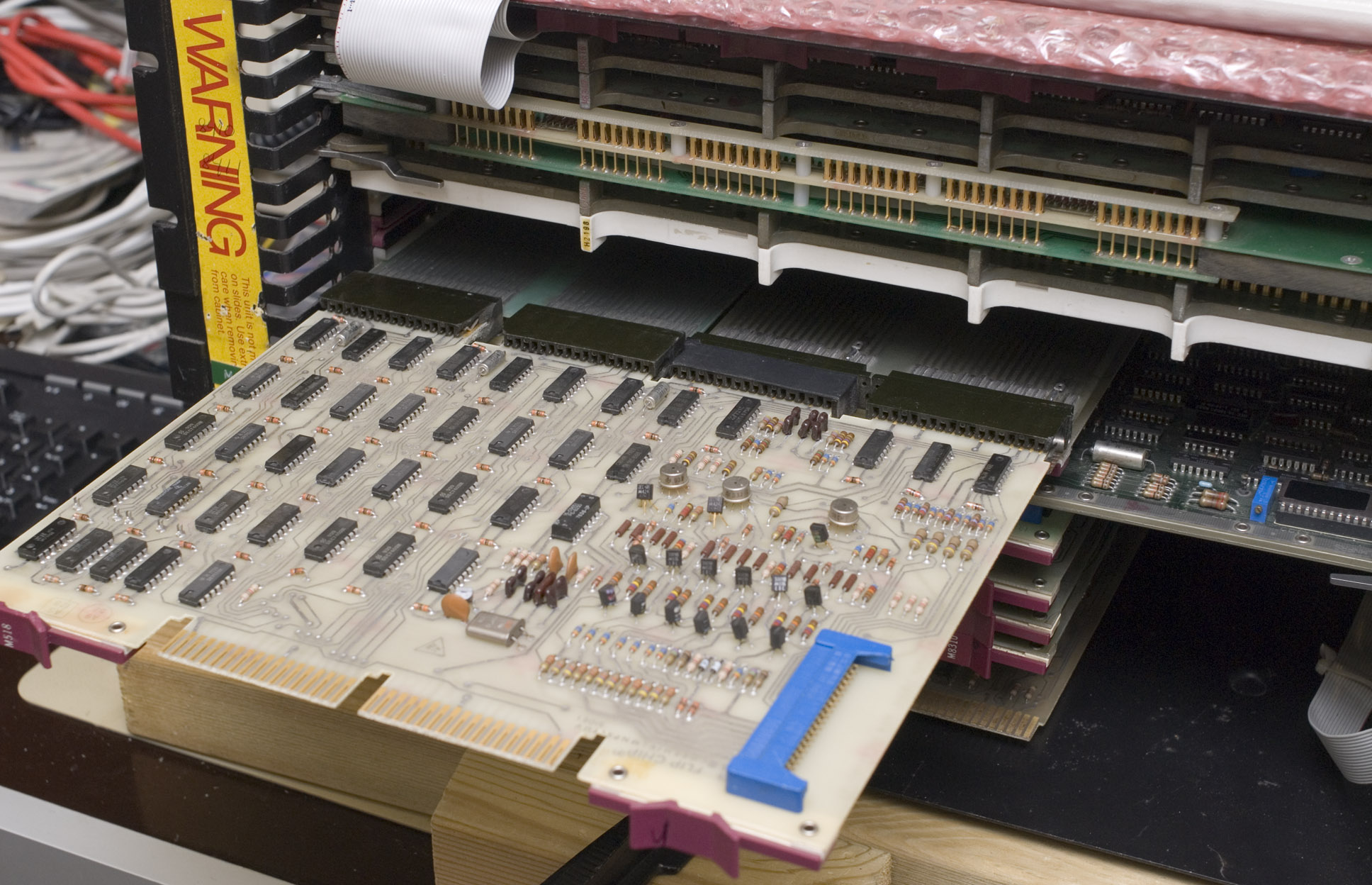
I haven't seen that document before. Thanks. But it doesn't cover the version of the BA8-C board that I have. Mine has the G8019 integrated on the same board. But it's interesting to see that the components around the opto and the transistor seams to match my patched board better that the schematics that I have. It's from the "PDP-8A Miniprocessor Users Manual" so it's older.

Early optos often brought out the base of the phototransistor so that the sensitivity could be adjusted. 4-pin isos came out later. I suspect a plain-Jane 4N28 will probably work fine--it brings out the base of the transistor. Datasheet.
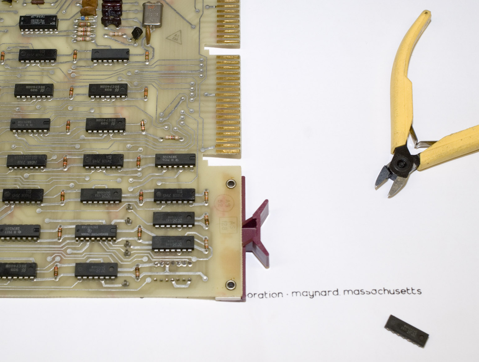
I'll try and see what happens. I'll just have to order the parts, since I don't have any of those at home.
 
I have now ordered the components (opto + transistor) from European Ebay sellers. When ordering from European sellers the stuff usually shows up within a week.
 
After I disassembled the 8A into small pieces I replaced the opto and the transistor. I used the 4N28 opto as suggested after I did some calculations and found it resonable. I replaced the transistor with the same part. The opto is sitting a bit under the transformer but it was possible to change it without unsolder the transformer. Look at the photo of the back of the PCB and it gets clear why, all those patch wires are glued to the back on the PCB.

After changing the parts I assembled a part and tried it and it worked! After this I have assembled the power part completely and now I just have to put in the logic PCB's again.

ba8c-front-part.jpg


ba8c-back.jpg


ba8c-front.jpg
 
I took out a M8655 (KL8JA) from the pile of tested omnibus cards I have. I checked it's configuration and changed it to use device code 40/41 and 19200 baud. I intend to use this together with os8serialDisk. I have also put all the logic cards back into the machine. I only got four slots free now. I plan to stick in the real time clock (DK8E two card set) in there and a EAE extension if I ever finds one.

Is it possible to extend the 8A with a expansion box from a 8E? I happens to have one, but no 8E.

I also wish I had a TD8E...

I have also compiled the serial disk software, it seams strait forward to get it running. I'll try it any time soon.
 
I found some pictures of the expansion box. It is a omnibus expansion of some sort, there where no photo showing a modell number. It holds two omnibus cards and some posibus converters(?).

M863 - DR8E, 12 parallel I/O
M8320 - KK8E, Busloads
M7101 - ?
M7102 - Posibus converters? (x4)

I have to bring this box home in order to examine it more.

Yesterday I tried os8diskserver and it just worked! Booted OS8 without any problems! Next step is to connect the RL01 drives again and build the system onto a RL01 pack.
 
I think you're right, I had a quick look in the DW8-E documentation and it makes sense.

I have learned small bits of OS8 and I have grabbed the next challenge in the pile of cards that I have. I have started to look at the DK8-EP real time programmable clock. I have tested it and I ran the diagnostics from os8diskserver, but without success. The test failed so I'll have to repair the cards.

I will also try to BUILD OS8 on a RL01-pack, but that will probably a new thread. I really don't know where to start.
 
Anders,

The RK05 disk image diagpack2.rk05 includes a batch file RLPACK.BI that will make a bootable RL01 diagnostic pack. You could boot from diagpack2.rk05 using serialdisk, then "SUBMIT RLPACK.BI", and within a few minutes your RL01 pack will be ready.
 
Thanks for helping me out!

It almost worked. I had to format the pack first, It came with a PDP-11 system but where never used (NOS). I ran pack verify first with success.

When I ran the batch file, it hanged when it should have copied the second side. Anyway, the machine booted from it!
 
I have fixed the DK8-EP option now. First I got a bit fooled, I tried to write my own program to test the boards but I got really strange results.

The instruction provided by the board set is:

Code:
CLZE=6130	/SET ZEROS TO CLOCK ENABLE REGISTER
CLSK=6131	/SKIP ON CLOCK INTERRUPT
CLOE=6132	/SET ONES TO CLOCK ENABLE REGISTER
CLAB=6133	/AC -> CLOCK BUFFER
CLEN=6134	/CLOCK ENABLE -> AC
CLSA=6135	/CLOCK STATUS -> AC, CLOCK STATUS IS CLEARED
CLBA=6136	/CLOCK BUFFER -> AC
CLCA=6137	/CLOCK COUNT -> CLOCK BUFFER, CLOCK BUFFER -> AC

But I got skip after CLCA. Strange. After quite some debugging I realized that DKC8A also had a clock option with instructions on OP-code 6135-6137. On mine DKC8A it was enabled so i turned it of and I reran the test. It failed anyway, but in different way.

M518.jpg

The M518 board. I couldn't get the clock to ran, but when measuring during the test program I could measure it on my oscilloscope.

M518-test.jpg

I put it on an extender so I could measure the clock. I then measured the clock from the crystal oscillator. Got the 1MHz out, but after that it is divided down by ten several times in the prescaler stage so it is possible to feed 1MHz, 100KHz, 10Khz, 1KHz and 100HZ into the counter. It was just the 1MHz signal that worked.

M518-ic_cut.jpg

I then realized that the second counter (the first divides from 10MHz) in the prescaler stage was broken so I replaced it.

M518-soldering.jpg

After soldering the replacement IC.

DK8E-PASS.png

Finally PASS!

Hope you like pictures!
 
Back
Top