• Please review our updated Terms and Rules here

TV Typewriter replica project back on track

The power transformer is pretty simple--two 12.6VCT secondaries. The good news is that this is pretty much a stock part even today. If you need help selecting, just ask, but probably 4A for each secondary would be more than adequate.
 
Thanks Chuck -- I think the real issue is the physical size of the thing -- having an actual board made now it doesn't look like the transformer is very big. Even the CT1024 one I have here is too large.

I'm pretty happy though with the way the boards are turning out.. I've got the toner transfer process down cold and am etching with vinegar/salt/peroxide. Works great and doesn't involve risking death handling the components.

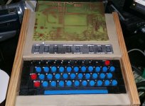
I've also concluded that we were both wrong about the construction of the case -- I think we had guessed metal for the back and wood or melamine or some sort up top. Since I know the real dimensions via the museum, it becomes obvious when I place the 'new' motherboard that it must be all metal, with the metal forming the top, back and front lip that is just in front of the keyboard. It's the only way it would fit and keep the top the depth that it is. With 3/4 or even 1/4 plywood there just isn't enough room underneath for the motherboard to fit. It has these 6 little l brackets, 3 on each side that it screws into the case with, front and back.

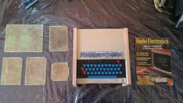
I'm happy with the color of the PCBs too.. I don't think they're quite a match for the originals.. but it's hard to say since photos kind of lie about color.

2016-06-19 21.56.27.jpg
 
On the rare occasion that I need a one-off PCB, I use hardware store muriatic acid and peroxide. Faster than the vinegar/salt stuff, and just as cheap--and way cleaner than ferric chloride etchant.

Are you tinplating your boards? There are solutions for that and they're easy to use.
 
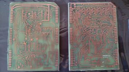
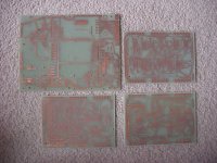
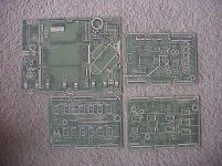
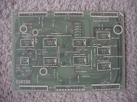
I don't think so.. here's a pic of what we believe are originals:

tvtboards5.jpg tvtboards6.jpg

I'm missing the close up shots I had, but there was definitely no tin plating. And it looked like SWTPC had some etching issues of their own, I remember on one pic of the mainboard there were a few solder bridges where traces must have been broken.

I sort of wish I could do the screen printing though. But, I would assume Don's prototype didn't have that, and I lack the technical know how to do silkscreening. It would help for parts placement though for sure.
 
The ones on the right are definitely tin-plated. There's a reason for doing it that way--it keeps the copper from corroding and provides a good already-tinned surface to solder to.

An example of plating solution

Kepro used to offer a kit that had two bags of powder to be mixed as needed. You just dunked the (clean) PCB in the solution for a few minutes and you were done.
 
The ones on the right are just the other side of the ones on the left.. all that's on that side is screen printed.

Hey.. still no luck on a 24 1a.. but I found this:

http://www.ebay.com/itm/130250605743

Having more amps doesn't matter right? This one has the wrong mounts... cant judge physical size.

I'm assuming Signal's model numbers had to do with volt and amperage..
 
Thanks for the tip Chuck -- I ended up messaging Signal Transformer directly and guess what -- they can still make the 24-1A (?!):

• The 24-1A is a custom modified version of a 24-1.
• The 24-1A is electrically equivalent to 24-1.
• The 24-1A is vertically mounted using a channel frame.
• The 24-1 is horizontally mounted using four “L” brackets.

I'm assuming the 'vertically mounted using a channel frame' business refers to that 'mounting style C' flange on their datasheet. That's what I need. I've asked him to clarify that it's exactly the same as one made 40 years ago. I'm surprised. It's a $44 set up fee and $48 each to build a couple, with 8 weeks lead time. Physical size is all I worry about at this point.
 
Well, I know that you're after historical accuracy, but the 24-1 seems to be a little lightweight for the purpose. Those old non-LS 7400 TTL ICs drink power something fierce. A 24-2 would at least give you a little breathing room--and according to the table, probably be indistinguishable from the 24-1 at 5 ft. But I know that you're less interested in engineering aspects than historical accuracy.

A "channel frame" means the "U" shaped metal bracket with "ears" surrounding the transformer body. The L-shaped brackets should be obvious.
 
Yeah I was thinking about that.. I'm assuming they must have a 24-2A or something similar with the correct mount. It's all about physical size really for me. This 24-1A would be brand new, so hardly historical. And obviously I have to go with new caps, although I might see if I can find old cap casings to hide them. It's amazing what just a few new caps did with my CT1024.
 
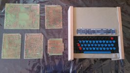
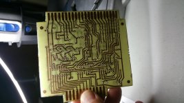
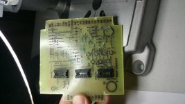
Got all my boards done!
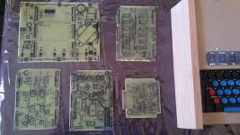
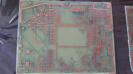
20160626_094712.jpg 20160626_100622.jpg

20160626_094824.jpg 20160626_100626.jpg

20160626_094850.jpg 20160626_100634.jpg

For years this has all been 'theoretical', although I did have the ICs. Having actual boards in hand kind of relights the fire. I've made 5 - the 'mainframe', the timing, cursor and memory board, along with one of Don's earliest ASCII encoders. He designed a few and there is one that came out I think in Nov 1973 -- I'm going to guess he used his original design, although he could have used a prototype of the new one. I like the slow vinegar/peroxide/salt etching process I found.. seems to be fairly gentle (although slow) and I've accidentally splashed some on skin and suffered no adverse effects. Had to remake a couple -- drilling on target is much harder than I thought, and it took me a while to find the best way to cut the boards to their correct side (carbide-tipped laminate scoring tool), so some have some chips from where I was using tin snips. The mainframe is a remake -- and I have to do some cleanup as I failed to put enough vinegar in and the etching process died out before it got all of it.

I have been making many discoveries about parts and so on along the way and slowly unraveling the 'mystery' of how it all went together in the prototype. As mentioned, I believe the case top, from keyboard to backside, is all metal. It became obvious looking at one of the mount points on the board (there are six small L shaped brackets you use to screw the TVT into place, upside down, in whatever case you have) that one of them was a ground, so you'd assume that would require metal. That and my pic of the back kind of put it over the top. I have the correct rocker switches, but I need two more that are momentary DPDT. Found those online pretty easily with correct switch plastic.

I've also found on Michael's site a UART project for the original TVT: http://www.swtpc.com/mholley/RadioElectronics/Feb1975/RE_Feb_1975_pg52.jpg

I'll probably build that.. would make the TVT a bit more useful. But not sure if I will integrate it into my existing prototype replica or try to use it in the replica of the cover unit I plan to build. I'm concerned that extra board might make the TVT too tall to fit under the prototype case.

I have all the ICs, which is great... I keep hoping to find 2524v shift registers that are 1973 vintage rather than 1976 like I have, but whatever.. I'm just glad I found any at all.

I did make one deviation from the prototype -- 'silkscreening' on the back. Looking at the blank backside I realized having this info for a newbie like me was vital. I have some White Toner Reactive Foil on the way that will transform the black toner transfer I did there to white. Think it'll look pretty good.

The PCBs aren't quite the shade of green I hoped for. That vintage green found on most old PCBs just doesn't seem to exist anywhere. it's either brilliant green or this 'natural' colour I've found. Oh well. Good enough I guess.

Pretty stoked to just get going and building!
 
Last edited:
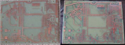
Here's a pic of the original and my newly made side by side. Actually, looking at it in pictures rather than in real life vs. picture, the color looks almost identical. The black from the toner 'silkscreen' on the other side will always be there unfortunately though -- I assume the toner reactive foil will coat the top but not change the bottom. Oh well. I think it's close enough, anyway.

tvtorigvsnew.jpg

Not bad!

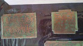
One thing I notice with the originals -- they have those little logo stamps on them -- they look like faint red M's. Here's one of the boards up close, if you look closely you can see these 'M's stamped all over:

tvtboards1.jpg

I'm assuming those are from the manufacturer of the PCB.. if I could I figure out who it is, maybe I could actually find original PCB stock out there, or something even closer than what I have.
 
Last edited:
Kinda looks like an 'N'. Going to look at my other SWTPC stuff later and see if they have any of those marks.
 
I'm inclined to believe pine is a) as others have noted, pine harvested 40 years ago is different than today and b) Don's whole thrust in this project was to keep the cost as low as possible. I don't know what oak and the like cost in the 1970s, but I know what it costs now and it seems like the Don thing to do would have been to go with cheap, aka pine. Then again, he knew this would be making an appearance in a magazine and elsewhere so maybe he went nicer.
 
The small amount of wood used in this project really doesn't bear too much on the cost--and prices for wood vary widely regionally. Where Don is, he might as well have made the box out of mesquite. Like most woods, it depends more on how the wood is selected and treated.
 
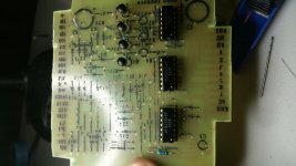
Well here's the beginnings of Don's original ASCII encoder. I figured I'd better start small and learn. I'm hoping I got the orientation of the first transistors right (2N5139). I noticed they have a flat side and I kind of looked at the magazine photo of the one Don built.

I'm using mostly vintage stuff.. but the resistors are brand new Chinese. I bought an assortment of them.. all look identical in size and color despite the different values. I'm kind of tempted to search for vintage ones but the whole project uses soooo many.. heh.

20160719_210632.jpg

20160719_211549.jpg

20160719_220324.jpg

Kind of fun, raising this thing from the dead..
 
Did film resistors exist in any quantity when Don's project began? I'm thinking that carbon composition resistors would have been most faithful to a reproduction.

Carbon-Composition-Resistor.jpg
 
Back
Top