• Please review our updated Terms and Rules here

Model I No Video

Fooser

Experienced Member
Joined
Jan 6, 2012
Messages
166
Location
Medford, OR, US
Another iron in the fire.

I have another Model I cpu/keyboard unit that has no recognizable video when turned on. It has a homegrown character generator with what looks like the Radio Shack lowercase mod. The daughter board seems to be firmly inserted into the socket.

From the Technical Reference Manual: I measured the voltage between the common side of C9 and the top side of R18 and I barely get 10V no matter how I adjust R10. It should be between 11.4V and 12.6V and it's obviously not.

Sams Computerfacts says to measure 12V at Z2 pin 3 instead which is harder to get to so I didn't measure from there. Should I? Is a Z2 replacement in order?
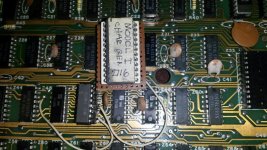
char-gen.jpg
 
Last edited:
Maybe pull the lower case ROM out of it's socket and check voltages with it out. It could be causing the problem.

Check Z2 pin 3 for a 12v reading also check pin 12 of Z2 or + side of C8 to see if you get the unregulated 12V input. It might be around 19V. Also be advised if Q6 starts going bad it can get very HOT!

If still low then there is a chance that the ROM is not the problem. Good luck & keep us advised.
 
Fooser,
You must get the +12.0 VDC correct before continuing on to setting the +5.00 VDC Power Supply and the -5.0 VDC Power Supply.

The +12 VDC and both 5 VDC Power Supplies powers the RAM. So, to remove the load of the RAMS, you can remove them from their
Sockets. That will allow you to see if the +12 VDC Power Supply comes up to +12.0 VDC and can be regulated. I'm not sure right now
where the +12 VDC also goes on the Model 1. It's likely you have some bad RAM, and they are likely HOT when powered up.

4116 RAM Chips
Pin 1 = -5.0 VDC
Pin 8 = +12.0 VDC
Pin 9 = +5.0 VDC

Larry
 
Last edited:
ldkraemer... one of the ram chips was indeed very hot and I replaced it with an identical one of the same brand. It did not heat up but did not fix the no video issue. I didn't try replacing the whole bank. I do have additional ram I can use if I need to.

Chromedome45... I pulled both the ROM and RAM. Z2 pin 3 gave me 16.5V and Z2 pin 12 gave me 21V. Again, adjusting R10 made no difference in voltage. The 16.5V is not within the recommended voltage spread of 11.4V - 12.6V. I didn't test for 5V as the 12V is out of whack. The power supply cube works great on other Model I's.
 
On page 75 of the tech ref manual is a list of voltages to be checked on the Z1 and Z2 regulators. That is where I would start.

One you have your voltages in spec, check Z41, an 8-pin device which can contribute to a dim display.

Ian.
 
Last edited:
What voltages do you have at:
Pin 12, Pin 11 & Pin 10 -- The book says Pin 12 - 21.69, Pin 11 - 21.16, Pin 10 - 12.31

Pin 6, Pin 5, Pin 4 -- The Book says Pin 6 - 6.92, Pin 5 - 6.92, Pin 4 - 6.92 (and Pin 4 should be adjustable with R10)
These are inputs to the Op Amp that control the Voltage of the 723.

It's possible Z2 (723C) could be bad, or Q6 (MJE34) could be shorted giving full output voltage.

The book has a good description of how the 723C works.

Larry
 
Ok here are the voltages for Z1 and Z2. I measured twice. As you can see, some of the voltages are way off.

Voltages for Z1 pins
1 - 0 should be 0
2 - 5.23 should be 5.30
3 - 4.94 should be 5.00
4 - 4.49 should be 5.00
5 - 4.93 should be 5.00
6 - 7.07 should be 7.46
7 - 13.3 should be 0
8 - 0 should be 0
9 - 0.29 should be 0.33
10 - 5.81 should be 5.89
11 - 16.61 should be 11.99
12 - 16.61 should be 11.99
13 - 6.98 should be 7.05
14 - 0 should be 0


Voltages for Z2 pins
1 - 0 should be 0
2 - 14.2 should be 10.60
3 - 16.3 should be 11.99
4 - 8.6 should be 6.92
5 - 2.2 should be 6.92
6 - 2.1 should be 6.92
7 - 0 should be 0
8 - 0 should be 0
9 - 10.49 should be 5.72
10 - 16.40 should be 12.31
11 - 29.90 should be 21.16
12 - 21.40 should be 21.69
13 - 0 should be 13.48
14 - 0 should be 0
 
Last edited:
Don,
Your Vref (Pin 6 of the Z2) Source output is way too low. It should be something close to 7.15 Volts from the Zener Diode inside the 723C.
You can double check the circuit trace around Pin 6 to R15 (1.2K OHM) to Pin 5 of Z2 (723C) just to be sure it all looks good, and nothing is
touching the trace which could cause a low voltage.

It looks like you will have to replace Z2 (723C) to get the proper voltage out of Pin 6 at about 7.15 volts.

This is all in the manual on pages 52 & 53.

The Vref of Z1 (Pin 6 is 7.07 VDC) which is good. I think if you get Z2 replaced and nothing else is faulty in the circuit you should be able
to adjust the +12.00 VDC and the +5.00 VDC, according to the voltages you measured.


Larry
 
Last edited:
I replaced Z2. I now have 11.9V at pin 3 of Z2 which is good. I have 5V at pin 3 of Z1 which is good. Unlike what the book says however, I have 9.5V at pin 7 of Z2 instead of 0V, and 13.1V at pin 7 of Z1 instead of 0V. I measured voltages with the ram and rom out.

And... still no video.
 
Last edited:
Fooser,
Pin 7 of Z2 is tied directly to the Common - Ground (same as Minus of C11), so you either have a bad solder joint or you have lifted a trace,
or you have broken the common connection some how. You have to find the problem and fix it. If you lifted a pad or broke the COMMON
connection from the top side circuit to the bottom side circuit that could do it.

Measure from the Minus of C11 to Pin 7 of Z2. It should be ZERO Volts DC. If not there isn't a complete path for the COMMON to Z2.
Measure from the Minux of C11 to Pin 7 of Z1. It should be ZERO Volts DC also.

With Power off you can also OHM the COMMON (GROUND) trace until you locate where it is broken. It shouldn't be too hard to locate.


Larry
 
On a suggestion from FrankG I connected Z1 and Z2 pins 7 to common (the right side of C9) and now all voltages read as they should. Getting excited, I inserted the ram and rom and... still no video.

Moving on, I figured I would disconnect one jumper at a time and see which one is open. Well, the plot... sickens. If I disconnect either jumper, I get voltages on pin(s) 7, although the voltages differ depending upon which jumper I lift.

Arrrgggghhhh!
 
Don,
If you have the Pin 7, floating problem fixed and the RAM and ROM inserted, and the Power Supply Voltages set correct, can you tell if anything is working?
Pin 6 of the CPU (Clock) have any activity? Address Lines Toggle? Data Lines Toggle? I'd think the next step would would be a NOP generator to
watch each and every Address Line Toggle. You can then scope them and make sure they are all working.

Larry
 
Don, If you have the Pin 7, floating problem fixed and the RAM and ROM inserted, and the Power Supply Voltages set correct,

I did get the voltages correct with the addition of two test jumpers. Are you thinking I should leave them in as the fix?

Pin 6 of the CPU (Clock) have any activity? Address Lines Toggle? Data Lines Toggle? I'd think the next step would would be a NOP generator to
watch each and every Address Line Toggle. You can then scope them and make sure they are all working. Larry

Haha well I'm afraid I don't have what it takes to accomplish that... wish I did. Thanks for your suggestions though. I'm very grateful.
 
Don,
As I stated previously, Pin 7 of both regulators is tied to ground, if the schematic is correct. You should be able to
locate where the problem is by chasing the ground trace to get to Pin 7 of each regulator. It has a problem
associated to that trace, and could well be the cause of no video because some other section of the ground
circuit could be floating too.


Larry
 
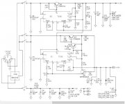
I verified continuity at each ground location indicated on this schematic.

As I mentioned before, when unplugged I do get grounds at Z1 pin 7 and Z2 pin 7. (see above) How do I look for an open ground trace from pin 7 when it's already showing a ground?

Plugged in I get voltages at both pins. When I jumper these pins directly to ground, the voltage goes away. Which seems to confirm an open ground! My layman brain is stupefied.

Model I Z1 and Z2.jpg
 
Don,
You need to clarify a couple of things.

You said, "I verified continuity at each ground location indicated on this schematic." If you are just checking for continuity you don't
really know how many OHMS or KOHMS each point is from actual ground plane. You really should be on a low OHM scale looking for
any OHM value greater than maybe 3 OHMS. The Ground Plane should actually be less than probably .2 OHMS anywhere you check.
I've never really had to check one it's just a guess.

Also, "As I mentioned before, when unplugged", what device/thing is unplugged?

With the Jumpers from Pin 7 To Ground lifted:

If you put your Meter on a LOW OHM scale, what do you read from Pin 7 of Z2 regulator to the Minus of C8, and the Minus of C11. What
OHM value do you have from the Minus of C8 to the Minus of C11.

Same thing for Pin 7 of Z1 to Minus of C9, and the Minus of C10. What OHM value do you have from the Minus of C9 to the Minus of C10?


Larry
 
I got my new meter today.

I have 0 ohms between Z2 pin 7 and minus C8. I have 0 ohms between minus C8 and minus C11.

I have 0 ohms between Z1 pin 7 and minus C9. I have 0 ohms between minus C9 and minus C10.

More Info:

I measured between minus C8 and minus' R14, R12, C11, C15, C28, C30, C32, C34 and had 0 ohms.

I measured between minus C9 and minus' R11, C10, C14, C1, C4, C3, CR2, C16-C19, C22, C23, C29, C31, C33, C35-C38, C40, C41, and C44-C56 and had 0 ohms.

I was unable to find CR1 to measure. :D
 
Last edited:
Don,
I just don't get it. Were all the points that you measured on one side of the circuit board versus being on both sides?
Maybe the trace for Pin 7 of the 723C is on the other side of the board? What we need is a circuit trace layout for both
sides of the board, like the Model 4 manual has. That would help a lot.

Larry
 
I measured almost everything from the component side of the board. In a few cases I could't get to the traces under a capacitor so i went to the solder side. Should I try all measurements now from the solder side? That will be slow going but if that's the next step, so be it.
 
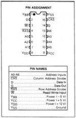
RAM IC Pinouts

RAM IC Pinouts

Don,
I'm not sure how much that would tell you, if anything. It would be interesting to do both the Pin 7's to
a good large ground plane area on solder side of circuit board to see if there is any resistance other than zero.


You might be better to solder both Jumpers from Pin 7 of both regulators back to the Ground plane. Then power up
the computer and go from a known good Ground Point with the Negative black lead, and check to the ground Pin
of every IC, looking for any type of positive voltage. I know it will take a while, but you will at least eliminate the
possibility of having some other IC's Common pin floating above ground. If you are not sure of the IC you can get
a cut sheet with the pinouts off the internet. But, the Model 1 Tech manual should have all the IC's ground pin
documented. I'd also check the three Power Pins of each RAM IC to all the RAM IC's. The Model 1 Schematic
doesn't have all the pins documented, in the first version.

Pin 1 = -5 VDC
Pin 8 = +12 VDC
Pin 9 = +5 VDC
Pin 16 = Ground


MCM4116.jpg


Larry
 
Last edited:
Back
Top