• Please review our updated Terms and Rules here

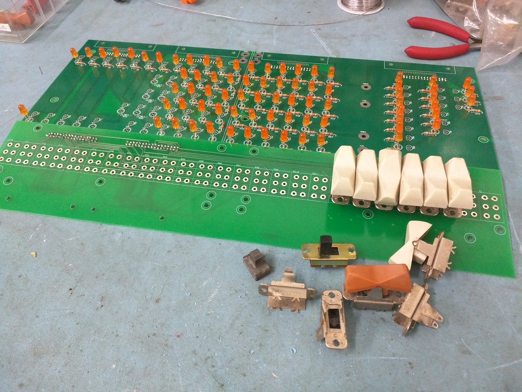
the smashed 8i resto project of sorts

1ajs

Experienced Member
Joined
May 27, 2005
Messages
452
Location
Winnipeg, Manitoba, Canada
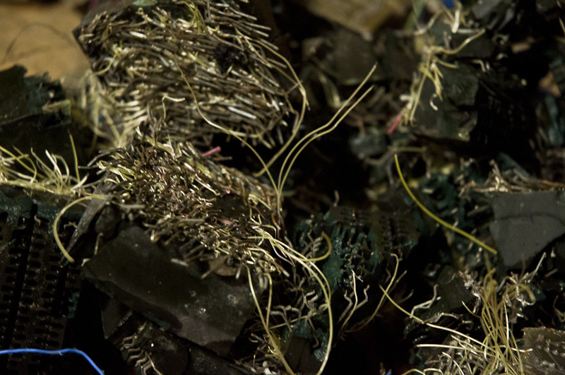
dunno if anyone remembers me posting a year ago about my find in a feild?
17183135472_b0c803aecd_b.jpg


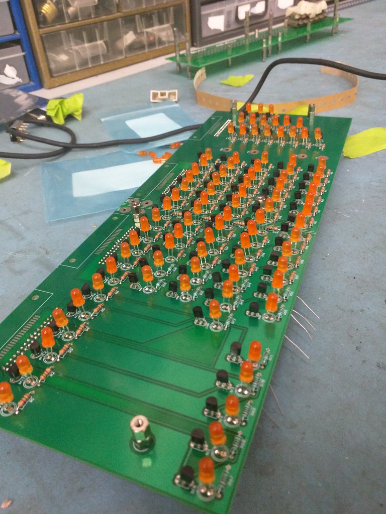
anyhow finally sat down to do some work on it about to order some more parts...


27863539914_a92d0264c7_b.jpg


also came across some newer but old slider switches im guna see if the local ewaste place can help me source a supply never know eh if succesful im guna look into making a bunch of the swivile parts for the plastic switches to sit on
 
Hi All;

1AJS, Excellent Work !!! Did You make the plot for the PCB and then have a fab house do one or did You do the Whole thing Yourself ??

Great Job !!

THANK YOU Marty
 
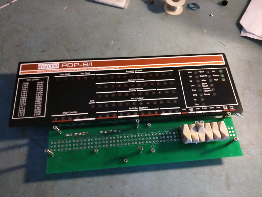
orderd me a replacement front panel for this project off the ccmp mailing list gues wont be till next month till i start working on getting materials together to make switches budgets allas but progress is sweet :)


then ill have to also look into getting a board printed for interfacing to a rasb pi that was allready designed by the same guy that i got the light board and replacement switch board off


untill then i dont understand how i should go about testing all the lights anyone have suggestions?
 
Looking real good!
-That first pic is probably the saddest I've seen on this site, though. It almost makes me forget how much I like that "Bus grantosaurus rex" image.
 
untill then i dont understand how i should go about testing all the lights anyone have suggestions?

I thought we had discussed the silkscreen having the transistors reversed. relative to the parts you bought?
Or did you end up buying different transistors?

Assuming the transistors are installed correctly, I think you can just supply bias current at the connectors to get the transistors to turn on.

Vince
 
i orderd the ones we discused
i just dunno what to do to make some lights turn on and test it
who things a learning experiance for me

OK, the transistors may be in backwards, but that should be apparent if you power the thing.
(All the lights will light, I believe, if their transistors are in backwards.)

As for testing, each transistors base is connected directly to one of the holes for the 34 pin connectors at the top. You need a source of +5V, and a suitable current limit resistor, of about 500 ohms -- DEC used 470 ohms. Connect one side of the resistor to +5V, then touch the holes with the other side of the resistor. Do *not* apply +5V to the holes without the resistor in between, as that will fry the transistor.

As you progress across the holes, each hole should light a bulb in a column near the connector. The exceptions are the ones with the fat traces in the middle of each set of holes, or no traces at all on the top or bottom, which are sort of scattered around. Regardless, you should be able to find a hole to light every bulb on the board.

This presumes you are able to power the board appropriately using the GND and +V connections.
What LED and current limit resistors did you choose? Those values determine the correct voltage for +V.

Hope this helps,

Vince
 
1500 ohm i beleave the led's i aquired worked with that from testing i did

One of the LED specs is the amount of current they are meant to operate with when fully on; usually 10 or 20 mA. There's also a spec for the voltage drop. These can be used to calculate the size of the resistor. Basically, the transistor is supposed to be either off or fully on, so it's resistance is ignored (or not, if one is pedantic). The diode also only needs a volt or two. For a 10 mA LED, each (additional) volt would require about 100 ohms, so about 1500 ohms for 15V. If yours are 20 mA LEDs, that would be only about half power for them. Of course, how much power you apply is also a function of desired brightness.

What voltage did you use for testing? The simplest thing would just be to choose that voltage.

Vince
 
Another, less hand-wavy way to think about it is that the design voltage for the indicators in a real 8/i is 15V unregulated. So, anywhere from maybe 20V during power up, to perhaps 12V if you tried to run all the bulbs, full on.

The same current runs through the transistor, the LED, and the resistor, since they are connected in series, and the voltage is divided up between them.

A typical inexpensive amber LED has a design voltage of about 2.1V. That means that, give or take just a little, the voltage across it will be about that.

The saturation voltage of a PN2222 transistor is about 0.3V, measured from emitter to collector while 15 mA is supplied from base to emitter. Adding those together, we get a little shy of 2.5V of relatively fixed voltage drop.

Subtracting that from the nominal 15V, we see that we want our resistor to drop about 12.5V.

Our typical amber LED wants 20 mA, so to get 12.5V dropped across the resistor would be 625 ohms. This is because resistors obey Ohm's law, requiring voltage to be the product of current and resistance.

You've got 1500 ohms, so you'd drive that LED with 8.3 mA, or about 42% of full power. For the LED data sheet I'm looking at, that is still about 3000 mcd bright, and probably fine. (It's also enough to light an old school 10 mA LED, some of which didn't get all that bright.)

On the other hand, running from a 5V supply would give a current of about 2.5V/1500 ohms, or about 3.3 mA. That's about 1/6 brightness, and would likely seem rather dim.

Part of the reason for 1500 ohms in my drawing was that it was a pretty safe value. Until you get into "fry the components" values, it's mostly going to work, and adjusting the resistor value is really more about making the LED you bought perform the way you want your panel to look.

Vince
 
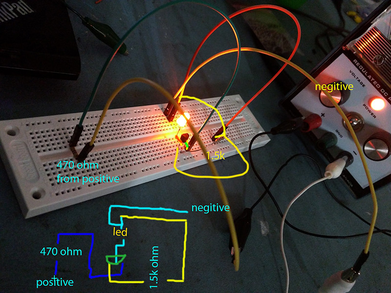
i cant get the led to come on if i use a ground if i put + - on it works on a test circut i built from reading stuff i dunno where to begin on the board

did some mucking but no idea if im doing it right

what i built to see things from looking around the net green as can be

29699178831_8857973fa7_b.jpg


edit just stumbled on this http://www.pdp-11.nl/homebrew/fullsize-pdp8/fullsize-pdp8-startpage.html
 
Last edited:
i cant get the led to come on if i use a ground if i put + - on it works on a test circut i built from reading stuff i dunno where to begin on the board

That looks all twisted around to me. Looking at the flat side with the leads pointed down, the pins on the transistor should go E B C from left to right, assuming they match the board's silk screen.

So, from right to left (to match the current):
C should go to the LED and the other end of the LED should go to 1500 ohms and the other end of that to +V.
B should go to the 470 ohms and the other side of that should go to +5V.
E should go directly to -V.

Hope that helps!

Vince
 
plus volts what ? and them +5 now im lost
On the board, where the spade lugs would go if you were using them, it says +V1 and +V2. These are actually tied together (hence +V). They can be +5V (for LEDs), but aren't required to be. The voltage on the resistor attached to the base of the transistor, however, is meant to be no more than +5V for light on, or 0V (GND) for light off. In your case GND should be the more negative lead from your bench supply.

I used the term +V before, when we were talking about which way around to install the transistors and why 1500 ohms was chosen for the resistor.

Vince
 
Back
Top