• Please review our updated Terms and Rules here

TRS-80 Model 1 RS-232

pavery

Experienced Member
Joined
Dec 29, 2008
Messages
160
Location
New Zealand
In the day, was there a popular & practical add-on that gave a cassette-based Model 1 the RS-232 function without buying an Expansion Unit?

Thanks
Philip
 
An outfit called Micromint made a stand-alone RS-232 box that was widely advertised, at least. There was also a fairly common 300 baud modem that directly plugged into the 40 pin expansion port… the name is escaping me which is sad because I actually had one of them. (Lost to time now.)
 
Thanks Eudimorphodon, that was the hint I needed. Further research shows Micromint produced the COMM-80 interface which included RS-232 & parallel printer port. This article describes the board in detail.

Philip
 
I am currently working on the schematic entry and PCB layout for a RS-232 interface that uses the printer port at 0x37E8. I've come up with an expansion port design that just consists of some logic chips for the address decoding, register latch and data bus buffering, a PIC micro to act as the UART, a MAX232 to drive the RS-232 lines and a DIP switch package to program the baud rate and mode of operation.

So LPRINT and LLIST will just "print" to the serial port. My main use for this will be for documenting my BASIC program listings - I'll be able to simply capture the output from the line printer commands with any decent terminal program on my PC.
 
Last edited:
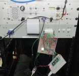
Probably hijacking this thread now, but this RS-232 project is something that I've had on the back-burner for a while now. Instead of getting back into KiCAD, today I knocked up a veroboard version of the design that I could kludge together with logic chips that I had at hand. This now gives me something functional to tide me over in the meanwhile and something to develop the PIC micro UART firmware on.

The final version will be all SMD and a much smaller board will take the form of an expansion-port dongle. As far as developing the firmware goes, this evening all I've done is coded a skeletal routine for the PIC to get the line-printer commands LLIST and LPRINT working. RS-232 transmission is interrupt-driven by the write strobe to port 0x37E8.

I found that the TRS-80 terminates each line with just a CR. To make this compatible with "modern" terminals, I had to detect CR and insert a LF. CR alone on the old printers would both advance to the next line and return the cursor to the left, but CR on many terminal programs just does the latter. Without a LF they will just keep overwriting the same line of text. In the final design I will assign one DIP switch position to enable/disable the insertion of LF.


rs232_1.jpg


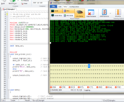
A BASIC program LLISTed to the serial port:


rs232_2.png


The terminal program allows the captured ASCII to be saved as *.txt -


1000 REM -LORENZ ATTRACTOR FOR TRS-80 LEVEL II BASIC 1010 REM -REQUIRES STAGE 1 MACHINE CODE GRAPHICS ROUTINES FOR 1020 REM -VGA VIDEO CARD B. WWW.GLENSSTUFF.COM 1030 POKE 16527,112: I=16526: X1=124: Y1=131: X2=138: Y2=145 1040 L2=203: POKE 28673,63: POKE I,64: A=USR(48) 1050 ST=0: C=0.01: S=10: R=28: B=2.67: X=1: Y=0: Z=20 1060 REM -COMPUTE, SCALE AND PLOT ATTRACTOR TO VGA SCREEN 1070 DX=(-S*X)+(S*Y): DY=(R*X)-Y-(X*Z): DZ=(-B*Z)+(X*Y) 1080 X=X+(DX*C): Y=Y+(DY*C): Z=Z+(DZ*C) 1090 PX=(X*12)+320: PY=(-Z*8)+450: IF ST=1 THEN 1110 1100 POKE I,X1: A=USR(PX): POKE I,Y1: A=USR(PY): ST=1 1110 POKE I,X2: A=USR(PX): POKE I,Y2: A=USR(PY) 1120 POKE I,L2: A=USR(0): REM -CALL DRAWLINE -(X2,Y2) 1130 GOTO 1070 : REM -NEXT ITERATION


I have a fairly convenient way of documenting my program listings now, transcription error free, I reckon.
 
Last edited:
There's various bits of info re serial printing from the cassette port in TRS8BIT. Vol. 1 Issue 2 page 3, and Vol 7, issue 2 page28.
 
There's various bits of info re serial printing from the cassette port in TRS8BIT. Vol. 1 Issue 2 page 3, and Vol 7, issue 2 page28.

Yeah, this came up in 80 Micro as well; apparently a lot of people had scrounged Teletype machines lying around back then. Usually the hardware interface (there wasn’t much to it) was set up for 20mA loop instead of RS-232. Bit banging serial out the cassette port was mostly okay for printing, but less so for bidirectional communication.
 
So LPRINT and LLIST will just "print" to the serial port. My main use for this will be for documenting my BASIC program listings - I'll be able to simply capture the output from the line printer commands with any decent terminal program on my PC.

FYI
There are a couple of other solutions for this already.

1. In BASIC, you can SAVE "filename",A to save the BASIC program in a text (A=ASCII) format to disk. Then, if you have something like a FreHD, you can use the EXPORT2 to move the BASIC text file to the SD card.
2. Virtual Printer Interface (https://www.plaidvest.com/newprint80/index.html). This hooks up directly to the printer port and your wireless network. You just web into the interface and when you print something, it shows up in the web interface. A simple copy/paste will allow you to get the code.
 
"There are a couple of other solutions for this already"


Perhaps, but those don't give me the general utility of RS-232 transmission and I like designing and building my own stuff, not buying stuff to just plug 'n' play.
That Newprint product isn't an RS-232 transmitter and it requires a printer port, so for a Model I that means that you need an expansion interface.

I think my RS-232 line-printer dongle is a lot more convenient and flexible than bit-banging RS-232 out of the cassette port. For a start, zero programming effort is required and no special routines need to be loaded into memory. You just plug in the dongle, connect a terminal, and then you are ready to capture the output of any software or BASIC routines that drive the printer port. My final design will do DIP switch selectable baud rates from 300 to 38400 bps.

I'll have this design fully documented and published on my site in maybe a month or two.
 
Last edited:
.... but less so for bidirectional communication.

Forgot to mention that my design supports that in hardware too. On the read side at port 0x37E8, the PIC UART has command of the full data bus, not just the four printer status lines D4-D7. An open-drain I/O pin (RA4) of the PIC is wired to the expansion bus interrupt line. That provides a means of signalling to the computer that a received character is ready to be read at 0x37E8. The TRS-80 can signal back to the UART that it has copied the character simply by writing back to port 0x37E8, though that generally won't be necessary. For the RS-232 port I have implemented in hardware lines RTS, CTS, TX and RX and I have assigned two DIP switch positions for configuring the mode of operation. The basic line-printer mode (that I have shown here) is/will just be a dumb transmitter only on TX with no handshaking. The other three programmable modes are left available for whatever one-way or two-way communications protocols I may wish to implement in the future.
 
Last edited:
Just a question about the Model 1 expansion port connector:

My Model 1 clone uses a high-density, 50 pin D-sub connector for said port, so 90 degree, PCB-mount version of that is what my RS-232 dongle PCB will sport. So that the design can be connected to an original machine without much bother, I am putting an appropriately wired 40-pin IDC header immediately behind the D-sub connector, which can be installed alternatively to the D-sub. I have read on the internet that +5V was available at pin 3 of the Model 1's expansion port only on early versions of the main PCB. Is that true?

I am just wondering if I will also need to provide a power source select jumper along with an alternative power input connector (and possibly a regulator/reverse polarity protection/etc) on the PCB.
 
Last edited:
I have read on the internet that +5V was available at pin 3 of the Model 1's expansion port only on early versions of the main PCB. Is that true?

The +5v is only supposed to be there on Level I Model Is; with the Level II upgrade they were supposed to cut the trace and convert it to a ground. I'm not sure there was ever a really good explanation for the change, but that's how it is. You should assume that there's no power feed available from the edge connector on most real Model Is. (I mean, I guess even if it is there because you have a Level I Model I it's not going to do you any good with a peripheral that emulates an printer port, given Level I BASIC doesn't have LPRINT/LLIST commands. Only officially supported printer for that machine was the wacky "Screen Printer" that DMA'ed data straight from screen memory.)

(To really make things confusing, the "buffer cable" mod for the Expansion Interface uses one of the pins on the EI's connector to supply the voltage to power the buffer back the other way, creating opportunities for shorting things if you use the wrong cable. Fun stuff.)
 
Last edited:
Forgot to mention that my design supports that in hardware too. On the read side at port 0x37E8, the PIC UART has command of the full data bus, not just the four printer status lines D4-D7. An open-drain I/O pin (RA4) of the PIC is wired to the expansion bus interrupt line. That provides a means of signalling to the computer that a received character is ready to be read at 0x37E8. The TRS-80 can signal back to the UART that it has copied the character simply by writing back to port 0x37E8, though that generally won't be necessary. For the RS-232 port I have implemented in hardware lines RTS, CTS, TX and RX and I have assigned two DIP switch positions for configuring the mode of operation. The basic line-printer mode (that I have shown here) is/will just be a dumb transmitter only on TX with no handshaking. The other three programmable modes are left available for whatever one-way or two-way communications protocols I may wish to implement in the future.

FWIW, if you really want to have full RS-232 bidirectional capability in your hardware it might be worth at least considering making this device able to emulate the actual port-I/O layout of the official RS-232 card in addition to your "pretending to be the parallel port" scheme.

(I'm pretty sure there was an article in 80 Micro describing how to route the parallel printer output in the Expansion Interface to be shadowed out the serial port to dispense with the need for a serial printer driver, so precedent certainly exists for making double-duty out of the single port.)

For minimal compatibility you'd probably just need to implement data in/out on port EB, (simulated?) status lines on E8, and some synthetic version of the UART status on EA. I *think*, but won't swear to this, that the Model I's implementation of the serial port was entirely polling driven, with a software loop just scraping the UART status flags to see if an incoming character was available; the expansion connector inside the EI does have an interrupt line but I don't think it was used by the card?

I guess this only really matters if you want to use existing TRS-80 terminal software, if you just want to write your own then whatever scheme you like should do.
 
Thanks Eudimorphodon, that was the hint I needed. Further research shows Micromint produced the COMM-80 interface which included RS-232 & parallel printer port. This article describes the board in detail.

Philip
Micromint produced a SBC based on HD64180 called smart spooler (I have 2).

These boards converted parallel to serial, serial to parallel (determined by sense switches) and supplied 256k buffer to buffer transfer.

Steve designed this project. As I recall, this project was his public introduction to projects based on HD64180.

I forget which copy of BYTE but in 1980s (I think).
 
The +5v is only supposed to be there on Level I Model Is; with the Level II upgrade they were supposed to cut the trace and convert it to a ground. I'm not sure there was ever a really good explanation for the change, but that's how it is. You should assume that there's no power feed available from the edge connector on most real Model Is. (I mean, I guess even if it is there because you have a Level I Model I it's not going to do you any good with a peripheral that emulates an printer port, given Level I BASIC doesn't have LPRINT/LLIST commands. Only officially supported printer for that machine was the wacky "Screen Printer" that DMA'ed data straight from screen memory.)

(To really make things confusing, the "buffer cable" mod for the Expansion Interface uses one of the pins on the EI's connector to supply the voltage to power the buffer back the other way, creating opportunities for shorting things if you use the wrong cable. Fun stuff.)

OK, good info, thanks for clearing that up. I've read that these things had heat issues with the power supply regulator. I'm wondering if the designer(s) just changed their mind about provisioning the thing to power peripheral devices; especially non-official devices that the computer owner could deny any knowledge of when making a warranty claim.
 
FWIW, if you really want to have full RS-232 bidirectional capability in your hardware it might be worth at least considering making this device able to emulate the actual port-I/O layout of the official RS-232 card in addition to your "pretending to be the parallel port" scheme.

(I'm pretty sure there was an article in 80 Micro describing how to route the parallel printer output in the Expansion Interface to be shadowed out the serial port to dispense with the need for a serial printer driver, so precedent certainly exists for making double-duty out of the single port.)

For minimal compatibility you'd probably just need to implement data in/out on port EB, (simulated?) status lines on E8, and some synthetic version of the UART status on EA. I *think*, but won't swear to this, that the Model I's implementation of the serial port was entirely polling driven, with a software loop just scraping the UART status flags to see if an incoming character was available; the expansion connector inside the EI does have an interrupt line but I don't think it was used by the card?

I guess this only really matters if you want to use existing TRS-80 terminal software, if you just want to write your own then whatever scheme you like should do.


Mapping the UART to the line printer address is such an obvious hardware possibility that I would not have imagined myself to be setting any kind of precedent here!

The intent with my simple RS-232 line printer dongle is to make the design as compact as practical and I wont be trying to emulate the original hardware serial functionality as well, with all the additional address decoding logic, configuration jumpers and/or a programmable address configuration register, etc. As mentioned, my primary intended use is line printer capture. That the design has full provision for two-way communications is just a bonus that comes with very little additional hardware complexity. Actually, I've already programmed the PIC UART with a basic receive mode. In the next evening or so I'll get around to testing it out by writing a simple BASIC program to POKE in the machine code required to shift received data into memory.

The original RS-232 hardware was poll-driven, and yes, a separately decoded address location was used exclusively for UART configuration and status - data was shifted either in or out on another address. I've only got one address, 0x37E8, for everything. If receiving 7-bit ASCII only, I could use polling too, by utilising the left over bit, D7, as a "new character in" flag, but that is no longer viable when receiving raw 8-bit data. Using a system interrupt to signal a received character is the obvious solution here. It cost nothing to connect an otherwise unused open-drain I/O pin of my PIC UART to the INT line.
 
Last edited:
It cost nothing to connect an otherwise unused open-drain I/O pin of my PIC UART to the INT line.

Uggh, not so fast. Unlike the Z80's non-maskable interrupt input, NMI*, the maskable interrupt input, INT*, isn't edge-triggered. INT* is active-low enabled. For Mode 1 maskable interrupts, INT* needs to be held low for long enough for the interrupt handler to disable interrupts and to RST to 0038H, but released any time between then and before your ISR terminates (with an EI (enable interrupts) and a RET (return) instruction), otherwise your ISR will trigger again and keep doing so for as long as INT* remains low.

It looks like I will need to latch INT* low and have it release when the ISR reads in the received character. The PIC micro I am using for the UART only has one edge-triggered interrupt input and I am already using that for synchronizing data transmission on WR*-0x37E8. If I had another such interrupt pin I could implement an IRS in the UART quick enough handle clearing INT* on RD*-0x37E8 whilst in the middle of receiving incoming data, but I don't and using polling to detect the ~500nS long RD*-0x37E8 strobe pulse whilst simultaneously decoding incoming serial data with a 200nS instruction cycle seems like a bit of a headache.

I am going to have to further complicate my hardware with a latch to assert INT*. The latch will be set by the UART after each received a character, and will be cleared by RD*-0x37E8.
 
Last edited:
I am going to have to further complicate my hardware with a latch to assert INT*. The latch will be set by the UART after each received a character, and will be cleared by RD*-0x37E8.


Got around to soldering in this latch this evening and I wrote a receiver test program in BASIC:

10 FOR X=1 TO 37: READ D: POKE 31743+X,D: NEXT X 20 DATA 237,86,62,195,50,18,64,33,19,124,34,19,64,251,201 30 DATA 243,201 40 DATA 0,128 50 DATA 229,197,33,232,55,78,42,17,124,113,35,34,17,124,193 60 DATA 225,251,201 100 REM -ENABLE ISR 110 POKE 16527,124: POKE 16526,0: A=USR(0) 200 CLS: REM -PRINT CHAR TO SCREEN 210 MP=PEEK(31761): IF MP=0 THEN 210 220 B1=PEEK(31761): B2=PEEK(31762) 230 MS=B1+(B2*256)-1 240 CH=PEEK(-(65536-MS)): PRINT CHR$(CH); 250 M=PEEK(31761): IF M=MP THEN 250 260 MP=M: GOTO 220


The program first POKEs three machine code routines into memory; these being USR routines for enabling and disabling interrupts and the actual RS-232 interrupt service routine itself.
The ISR just dumps received RS-232 characters into the top 32 KB of RAM (my model 1 has the full 48 KB)

A BASIC language routine then starts at line 200. This routine continuously polls the least significant byte of the address pointer used by the ISR to store the received characters. If there is a change, meaning that a new character has been received and stored, the character will be read from RAM and printed to the screen.

So I can type text to the TRS-80 video screen via RS-232 by typing into the terminal program on my PC:


1656173134249.png


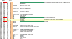
Here is a breakdown of the machine code:


1656173203986.png
 
Last edited:
Just waiting on the PCB manufacturing now. I think I'll have to do a similar device for the Commodore PET next (line printer on the IEEE-488 port to RS-232).

1656543555552.png
 
Back
Top