• Please review our updated Terms and Rules here

RTC Clock setting on Heath/Zenith Z-148 PC

fdiskitup

Experienced Member
Joined
Mar 2, 2022
Messages
247
Location
Chicagoland, USA
After a couple of fruitless evenings googling I’m back here begging for help.
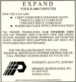
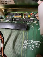
The Z-148 has a third party expansion board, like this pic,
“premier technologies, inc” board is Z148X , the rtc chip is MSM58321.
I’ve tried several of the clock applications from the rtc section on minuszerodegrees.net but no luck.
0F1BF935-343C-4DBD-8C07-7DC4AD6F6F3C.jpeg
Here is what the Premier Technologies manual says
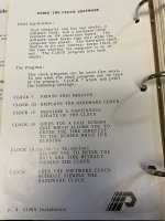
00001CDE-4685-4F46-B975-4698702BD777.jpeg
So is there a way to set the hardware clock?
My fundamental understanding is still limited, but surely its just a case of pushing a few numbers into the right memory location ? Could it be done from debug ?
 
... the rtc chip is MSM58321.
I’ve tried several of the clock applications from the rtc section on minuszerodegrees.net but no luck.
Did that include the Boca Research one?

The Boca Research one is written for a chip, the RTC-58321, that, from datasheets, appears to be the MSM58321 with a built-in oscillator.
Therefore the Boca Research one may work if the RTC in the Premier Technologies board sits at the same range of I/O ports that the Boca Research RTC software is written for.
 
Last edited:
My fundamental understanding is still limited, but surely its just a case of pushing a few numbers into the right memory location ? Could it be done from debug ?
Yes, but to I/O ports, not memory.

One would need to know the range of I/O ports that the MSM58321 RTC chip in the Premier Technologies board sits at, and interpret the MSM58321 datasheet in order to work out what instructions and data need to be written to those I/O ports.
 
Very close !
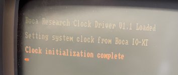
It didnt like dos 2.1 at all so I made a blank dos 5 boot disk.
Coppied the boca driver clock.sys to this disk.
Created a config.sys file with 1 line
Device=a:\clock.sys
This seems to load at startup!
F88AF3F5-14F0-460A-930B-A9A7B2F9ACD6.jpeg
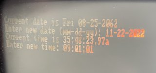
But now we are in the year 2062 (after the alexa uprising), and it is 35 o’clock…
C951645E-2B88-4A89-BEE3-599215FE7737.jpeg
With the clock driver loaded “time” and “date” dont change anything.
I.e I cant set the software clock, because its synced to the hardware clock by the driver clock.sys
How can I set the hardware clock?
Is there documentation ive missed or a setup disk for the boca card?
 
correction: setting the soft clock is possible with the clock.sys driver loaded. just the date remains stubbornly at 2062.

also CMOS battery is 2.75V which seems a bit weedy but it should work down to data holding voltage 2.2 V, battery was new (digi-key) 2 days ago but I did not measure the voltage when I installed it.
 
The Zenith rom has a monitor program that I can access before boot, this allows me to interrogate ports, and set them i.e. I 1F reads the value from port 1F (I think), similarly, -> O 1F should allow me to send a value to the port.

poking around with David_M's universal "clock.com" reader, using a force switch -

Clock u f18

returns the banner, and "Real time clock type MSM-58321 forced at port address 02C0H"

is that a clue to the port address ? (although this tried it did not set the RTC).

clock d f18

returns the garbage date 2065 and time 36:xx:xx.

clock d

tells me there is no real time clock

(also checkit 3.0 can't detect a real time clock).
 
returns the banner, and "Real time clock type MSM-58321 forced at port address 02C0H"

is that a clue to the port address ? (although this tried it did not set the RTC).
No.

It is not possible via software to configure the MSM-58321 chip to sit at a particular base I/O address. That address is controlled by other chips on the RTC card. The "forced" makes sense to me if David_M's software normally tries to auto-detect the base (starting) I/O address of the RTC card, but either the auto-detect mechanism causes problems, or the auto-detect mechanism cannot locate the base I/O address of the RTC card. If that is the case, and the user is aware of the base I/O address of the RTC card, then the user can "force" the software (repeat: software) to use a particular base I/O address.

At this time, you do not know the base I/O address of the RTC card.
 
(also checkit 3.0 can't detect a real time clock).
There is no international standard (hardware or software interface) for RTC functionality in the PC family. There are different types of RTC chips (configured and read differently), and the hosting RTC card (or motherboard) may have the chip sitting at any base I/O address. I doubt that Checkit knows about all of those variations. Checkit may simply be looking only for the RTC found in the IBM 5170 (and 5162) (and AT clones).
 
Stupid question here--have we tried probing using DEBUG or a similar program while watching using a logic probe on pins 1 or 13 on the RTC clock? That would nail down the I/O address. They're normally low (either or both of them) and a hit would register one going high. Your logic probe should have a pulse catcher on it.
I'd suggest probing all I/O addresses using a byte read (IN AL,DX instruction) every 16 addresses starting with 200h and going to 400h (i.e. probe 200h, then 210h, 220h, etc.) There aren't that many of them.
What is a bit odd is the cap on pin 2 to ground (WRITE). Perhaps to stretch a pulse?
 
Clearly I will need to go away and do some reading, learn assembly language, etc. It looks like there was a thread in the past for a Leading edge model M that had a similar issue.
1669164115960.png
I see the logic behind probing pins 1 and 13, I'm just not sure what command(s) to send in debug to get a "hit" though.

I would need to write a program like :

LD DX, 200h - load the port address 200h into DX register
IN AL,DX - copies the value at port address DX into register AL - forcing the state of pins 1 and 13 to change
RET - return to dos

probably useful to set up a loop.... ?
 
If you have the time and would enjoy writing a debug script I would be grateful, and I might learn something. Those S-100 homebrew guys did this type of thing all the time, but first they had to build the card.. at least we have the card.

my alternate approach is to use GWbasic OUT command to send stuff to the ports, or INP to read the ports and look for the one that increments every second.
10 For portaddr= 200h to 400h step Fh. (512 to 1024 step 16 decimal)
20 PortValue=INP (portaddr)
30 Print PortValue;
40 Next portaddr

I’m only doing this for a challenge, its not like I really need a working RTC in a 40 year old pc clone.
 
I wish I had one of these cards in my Z-148. It's a neat little system, but not having any ISA slots absolutely cripples it.
 
A BASIC program will certainly work; I'll leave it to you. However, I'd recommend that you pause after each probe (and perhaps probe each address a number of times). You could even be selective about what key was pressed to continue; i.e. "N" would advance to the next address; "R" would repeat the current one. You could also vary the step size; say, by 8 instead of 16.

Have fun!
 
I wish I had one of these cards in my Z-148. It's a neat little system, but not having any ISA slots absolutely cripples it.
Yours is the only other I’ve seen on youtube. Deserves its own special !
The Heath/Zenith, Z-100 / Z-100 PC, thing is pretty confusing.
I got lucky, 2 slots is perfect for a network card (mTCP) and an XT-ide.
 
Attaching the expansion card "manual" for what its worth.
 

Attachments

  • PT-Z148X Installation and Clock setup comp.pdf
    685.5 KB · Views: 5
Ok, a couple of updates.
The ISA part of the card works (both slots tested with an XTIDE card - the XTIDE bios shows up onscreen so that's good).

The pins 1 and 13, on the MSM58321RS clock chip, are both set to high all the time. This seems wrong.
The new 3V coin cell started at 3.3V, now reading 2.8V after only a couple of days... but for measurements the power is on so not important till I figure out how to set the clock. However, this might be an indication battery of drain to ground, a bad 4.7 uF capacitor (shorted Tantalum?)

For the logic probe I'm using the 5V from the floppy molex connector and ground on the chassis (probe is set to TTL and mem mode for fast pulses).

There is a 1Hz signal on pin 10 (BUSY) - so the clock chip is doing something.

In addition to the capacitor hanging off pin 2 (Write) the pins 11 (STOP) and 12 (TEST) are connected by a bridge piece.

My probing experiments did not yield anything yet.
 
"The pins 1 and 13, on the MSM58321RS clock chip, are both set to high all the time. This seems wrong. "

Perhaps not. Try putting your probe on pin 3 and repeating the test--and start your probing at port 100h.
 
Back
Top