• Please review our updated Terms and Rules here

PET reset switch circuit with a condensator for pulling the diagnostics line down

AndyG

Experienced Member
Joined
Oct 11, 2016
Messages
394
Location
UK
Hi all, quick question, Pronto-PET had a neat little reset switch which on a quick press performed a reset but if you held in the switch it would pull the diagnostic line down and reset the pet into monitor mode. All mounted in a compact box.

Anyone got a circuit diagram for such a reset switch or the best design for a compact circuit?
 
it’s in a very small box maybe 1.5cm by 3 cm … only connections on the motherboard are pin 22 j4, pin 25 j4 and pin 20 j9
 
Last edited:
Have you got a link to any photographs or anything?

I have done an internet search - but just found the adverts in magazines. It cost £9.99 though!

Dave
 
Have you got a link to any photographs or anything?

I have done an internet search - but just found the adverts in magazines. It cost £9.99 though!

Dave
Same here … the circuit is enclosed in the small box and do not want to dismantle as could damage it…. There is a Google discussion forum and someone who hosts the portcommodore website apparently posted a pdf but I cannot seem to find it….


I have built a 2 switch box where when you depress the “diagnostic switch” it pulls the diagnostic line to ground and then you tap the reset switch… that pulls it into the monitor… ideally I would like to replicate the Pronto-PET solution

andy
 
Last edited:
Ah, Olaf's text makes it now obvious...

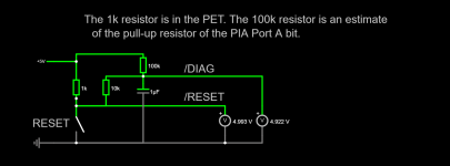
You have a conventional normally open pushbutton between 0V and /RESET. The pull-up resistor is on the PET board of course.

You then connect the /RESET signal to the DIAG pin via a capacitor. The trick is to find the correct value of the capacitor to do the magic trick.

Ordinarily, the DIAG pin will be pulled up to +5V (via the internal passive resistors built into the 6520 PIA port A).

Pressing the RESET button briefly will cause the CPU (etc.) to reset - but will not make much difference to the charge on the capacitor feeding the DIAG pin.

Pressing the RESET button for a longer period of time will cause some action on the capacitor. I will model what will happen in SPICE if I get a bit of free time...

When the RESET button is released, the CPU will start executing but (hopefully) the DIAG pin will still be LOW as the capacitor tries to charge up.

However, having just written this - I see I am a little confused about how this is going to work - so I will need SPICE to help me here!

Dave
 
Hi,

I have used something like this previously with other systems. Will it work? IDK. IF you have access to only the ground line and the DIAG and /RESET lines something like this "should" work, though I am waiting for the electrical engineers of the group to swarm and pounce once I post this:
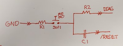
PET_DIAG_SWITCH.jpg

R1 and R2 are for current limiting purposes, so can be something like 470 ohm, start with larger values and work down till you can trigger a reset condition with a short press. This will depend on the pullup resistors that keep these lines HI normally. IDK what those are. So some futzing is needed. Start with a larger value for C1 and work down, 22uF is a good guess. Large values will require a longer press to trigger the diag condition.

At power on, C1 is unbiased, and both DIAG and /RESET are driven high in tandem by their usual pullups.

A short press causes C1 to charge from /RESET. How fast it charges depends on the pullups on /RESET, R1 and C1. A short press biases C1 slightly, but not enough to maintain DIAG LO long after release.

A long press causes C1 to charge completely at which point the pullup for /RESET will drive /RESET HI, but DIAG is still driven LOW by you holding the switch. So if you keep pressing the system will reset - hopefully in diag mode. The time to reset can then be adjusted by using a larger / smaller C1 value. Releasing the switch at this point does not matter, /RESET is already high, C1 is biased to drive it high and drive DIAG LOW. So basically, "hold till diag" The time constant for the chosen C1 may be very long. So patience.

Also... will this work? IDK.
 
Copy the attached into https://www.falstad.com/circuit/

Code:
$ 1 0.000005 10.20027730826997 50 5 50 5e-11
R 96 48 64 48 0 0 40 5 0 0 0.5
g 96 224 64 224 0 0
s 144 160 144 208 0 1 true
r 144 80 144 128 0 1000
w 96 48 144 48 0
w 144 48 144 80 0
w 144 128 144 160 0
w 144 208 144 224 0
w 144 224 96 224 0
p 464 144 464 208 3 0 0
w 464 208 464 224 0
w 464 224 144 224 0
w 464 144 144 144 0
w 144 144 144 128 0
r 288 32 288 80 0 100000
w 288 32 144 32 0
w 144 32 144 48 0
p 544 144 544 208 3 0 0
w 544 208 544 224 0
w 544 224 464 224 0
w 544 144 544 80 0
w 544 80 288 80 0
c 288 96 288 128 0 0.000001 4.902905952841901 0.001
w 288 96 288 80 0
x 376 133 462 136 4 24 /RESET
x 376 72 441 75 4 24 /DIAG
r 208 80 208 128 0 10000
w 288 128 288 224 0
w 288 224 144 224 0
w 208 128 208 144 0
w 208 144 144 144 0
w 208 80 288 80 0
x 50 190 130 193 4 24 RESET
x 161 -35 813 -32 4 24 The\s1k\sresistor\sis\sin\sthe\sPET.\sThe\s100k\sresistor\sis\san\sestimate
x 178 -5 626 -2 4 24 of\sthe\spull-up\sresistor\sof\sthe\sPIA\sPort\sA\sbit.
o 9 64 0 4098 5 0.1 0 1
o 17 64 0 4098 5 0.1 1 1

The time constants are a bit too slow at the moment - but the principal is there...

1685122872538.png

Dave
 
This may not be 100% correct.

At a power-on condition, the capacitor would be fully discharged and would have to charge up via the pull-up resistor of the PIA. As a result, the PET may enter TIM.

I'll keep thinking - and simulating...

Dave
 
This may not be 100% correct.

At a power-on condition, the capacitor would be fully discharged and would have to charge up via the pull-up resistor of the PIA. As a result, the PET may enter TIM.

I'll keep thinking - and simulating...

Dave
Thanks Dave….. I guess the 5v comes from the reset line when it pulls up high on pin 22
 
Yes, the 5V is the PET +5V and the 1k resistor is the pull-up resistor on the PET.

I have to include them in the simulation...

Dave
 
I made one of these for my first PET but unfortunately I sold that one and don't have any notes; ISTR that it was a little simpler than what's proposed so far though, but I could be wrong.

On my later PETs I used some dual-pole buttons that could have the trip point adjusted independently (they use tiny microswitches); press slightly for the first click to reset, press a little harder for the second click and the monitor.

But aside from drilling an extra hole the two-button approach is just as simple.

m
 
This is an interesting thread.

It would be ideal to have a simple circuit which had predictable timing for the time it took to distinguish between a short and a long button push. One way to do that with very few parts is to use a capacitor charging in the gate of a mosfet (a BS270 is fine) Because of the insulated gate you can use a low value capacitor like a 1uF MKT and a 1M charging resistor or similar, to make the "timer". The gate of a cmos 4000 series IC is similar and if say a NAND gate IC is used it has the option of configuring the logic output with the spare gates to suit the task exactly as well as the analog timing requirement.

I'll do some experiments on my PET and see what happens.

Opinions on this A or B or C better for diagnostic purposes please:

A) a short button press goes straight to Monitor mode and the long press globally resets the PET, then another short push would take it to the Monitor etc ?

(suggested reason: if something has gone wrong with some program execution, it would be better to go directly to the monitor to help diagnosis, looking at registers, PC etc, rather than the hard reset which would alter these and going to the monitor represents more of a partial than a full reset ?)

B) the short press resets the computer as in the original post and the long press BOTH resets the computer and then invokes the monitor after that reset when the computer boots ?

In other words would it be better if the short and long button presses were uniquely decoded to have independent control over the two operations, or not , or have the long press doing a sequential effect as in B?

C) a better scenario that I have not thought of ?
 
Last edited:
Yes, the 5V is the PET +5V and the 1k resistor is the pull-up resistor on the PET.

I have to include them in the simulation...

Dave
Ok, think will breakout the breadboard… in a box somewhere, (the last time I used it was to do a silly test over covid on a new piece of equipment we were preparing for launch … testing the analog output interface board from a measuring device into an Arduino, scaling the digital output and wiring it to the user port of a 2001-8c….State of the art measuring device outputting on a PET 2001-8c But I digress)

Andy
 
I just answered my own questions checking on my PET. The /diag line does not put the PET into the Monitor mode if the PET is already booted. If the /diag line is held low, then the PET boots to the Monitor only after a hard power up or a reset of the PET's 555 timer.(I'm sure everybody else knew this !)
 
If you look at the PIA line used for the /DIAG signal, it is also an output (it drives the sounder).

It starts off as an input and then becomes an output (in my mental model anyway).

Dave
 
I just answered my own questions checking on my PET. The /diag line does not put the PET into the Monitor mode if the PET is already booted. If the /diag line is held low, then the PET boots to the Monitor only after a hard power up or a reset of the PET's 555 timer.(I'm sure everybody else knew this !)
I found this out also with the two switch solution ….
 
Back
Top