• Please review our updated Terms and Rules here

1541 Mitsumi drive operating way too fast!

VERAULT

Veteran Member
Joined
Jan 30, 2012
Messages
8,467
Location
Connecticut, USA
of the things I picked up at the VCF swapmeet, I got a couple broken 1541 drives pretty cheap. This got me thinking to go through the ones I had and make sure they all work. OF the two drives I picked up, one turned out to be an alps drive. The first I have ever seen or worked on as every single other one has been mitsumi. The alps is interesting as its the same drive mechanism in the later half height Apple II 5.25" floppy drives.. Ok Im meandering.

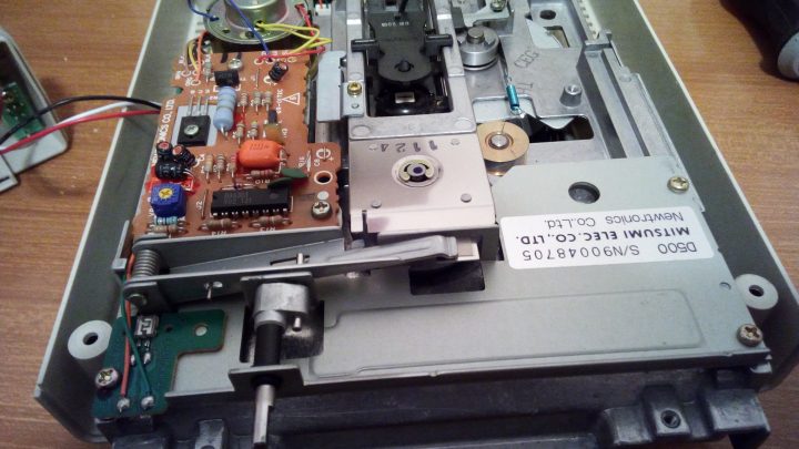
One my my drives that is mitsumi has a good board but when I run diags on it it reports it way too fast 500+rpm. If I use the pot to change it it can go much faster but I cannot get it to register less than 500+ RPMS. The adjustment pot when turned kind of easily flips over and doesnt stop. It could be a problem but I wanted input from the rest of you what to do in these situations.

What should I check first or is this a known fix?
 
now I'm definitely no expert on this, but does the drive self report the speed? if so, does the actual drive have one of those rings on the bottom of the spindle that can be used to visually verify the speed?

sorry if this is no help
 
I'd set it at 600 and call it a double speed drive! LOL. If it works, why fix it, esp if its faster. Unless its throwing out errors why worry...
 
Last edited:
It doesnt work, Why do you think I made the post?! The disk can read contents but If I try and run or exacute anything it just starts blinking red. I am using the 1541 diag tools to get the speed. And I can attest that it sounds too fast.
I take you guys never worked on a 1541?
I have repaired plenty and I can tell you drive speed is practically not an issue with 1541 drives (from all the ones I have seen anyway, that is why this is strange.
 
Having fixed some wonky drives over the years, I look at the caps driving the motor. Look at the ones around 47uf or so closely. I fixed a few sony drives that way.
 
According to this: its a Newtronics mechanism that regulates board speed. Anyone know the value of the trimmer pot? I doubt it the main culprit, but like I said its "slacky"
IMG_20170318_092914-720x405.jpg
 
typing on a difficult phone AWAY FROM HOME ...but I have a lot of experience with motor servo control systems especially for DC motors, i don't have the schematic on me, but the usual M/O for good speed control is to have a tachometer on the motor shaft (perhaps the yellow wires) that produces an AC frequency proportional to motor speed which is then frequency to voltage converted and fed into the negative input of the DC servo amplifier (typically) op amp ,which ultimately drives the motor via a transistor output stage, so it is a negative feedback system. If this tacho pathway/signal goes AWOL then the motor will run to near full speed.
So check the continuity of the tacho winding And signal from the tachometer (with the scope) and that this signal makes it to the ic .
 
Looks the IC is the Sony CX-065B.

The data sheet on that IC would show its internal contents. By the look of it, they feed the full wave rectified (now pulsed DC) from the Tacho coil into the IC. The IC will likely contain the frequency to voltage converter and the OP amps. Generally with this arrangement the speed control voltage feeds the positive input to the servo amplifier and the DC level from the Tacho F to V converter into the negative input. It would be easy to check with the scope if the IC was receiving the tacho signal.

Of course other possible explanations could be shorted output transistor (Q4) running the motor to full speed that way.

It would pay to check all of the capacitors around the IC before assuming the IC is defective, one of them will be the filter for the F to V converter.

Also check to see if C9 (a tant cap) is shorted out as this would bias on the output transistor. And a leaky or shorted C7 will turn on the driver transistor, so both those Tants could be the culprit.
 
Last edited:
Got to be worth trying to replace the trimmer pot or the newtronics control board first - there are a lot of drives out there with dead heads so I would've thought it may not be too hard to obtain. I don't know the pot value I'm afraid. I had an alps with a very slower spindle motor, but it must've had a winding short because the resistances measured very low. Also had a Master-41 where the Hitachi motor control IC had failed, but that resulted in no spindle movement at all rather than a speed up, so my money is on the passives.
 
On an off note, hope to goto Vcfest Midwest this year, hopefully, maybe? Been saying that for 7 years I digress... Was going to go in 2020 then ... well... ya.
 
Dumb question, but have you checked the power going to the drive vs what is expected by the drive? A possible answer seems to be it may be getting to much power (bad resistor maybe) and it is causing the drive to just be overpowered.
 
The mainboard of the 1540 is fine., I swapped it with another Robert. That is where the PSU is. The issue is only on the drive. My guess is the newtronics board as well. I would swap it but parts for Commodore drives are nowhere near as easy to come by these days... for a decent cost. Thas why I wold rather fix it.

I bought some 20K trimmer pots to fix the one on this board https://www.ebay.com/itm/113743347522
I doubt it will fix the issue but this one is too loose. I will replace it, recap the few caps on the motor board and go through the rest after.

Can someone recommend a suitable replacement for the 2sb703 TR1 transistor? They arent cheap.
 
Last edited:
Can someone recommend a suitable replacement for the 2sb703 TR1 transistor? They arent cheap.


For this application you could use the common garden TIP42B or TIP42C.


Looking at the schematic though, while it is possible, it is not very likely the transistor is defective, because it has another transistor wired into its base circuit that acts as a current limiter, even if the motor terminals were accidentally shorted out, or motor stalled, that the transistor's max current would be exceeded. It is also a 80 to 100V rated part, and it is unlikely that the small motor would have produced enough of a voltage spike to destroy it, so the transistor is very well rated for its task, but it can still fail.

In order of probabilities I'd suggest C7 or C9 short or leakage, tacho winding possibly open, output transistor shorted, IC failure etc, but in electronics, any part can fail at any time so it is all guess work until the fault is tracked down by testing components, voltages & signals in a logical sequence. At least the transistor is very easy to check on a meter.
 
Last edited:
Thanks Hugo. I dont keep a large assortment of transistors on hand to be honest just these:
semiconductors.jpg

But what you say makes perfect sense.
Ill do the caps for good measure and I found on page 23 of the service manuals resistance checks, so I will be sure to do those as well.
 
I can't see any transistors on that list off hand that would work, but I am not familiar with some of them.

One simple test, to help narrow down the general location of the fault, would be to check the output voltage on pin 5 of the IC with the motor running:

If the fault is in the IC / tacho circuit this voltage will be high, at least a few volts or more, as the IC will be instructing the driver stage Q2 and output stage Q4, to conduct and thereby run the motor fast.

However, if the fault is in the driver and output stage transistors themselves (or the caps C7 and C9 leaky/shorted), then the IC will be trying to slow the motor down and the voltage on pin 5 will probably be one volt or less perhaps below 0.7V.
 
Last edited:
Ok. So I have done some work on this drive. First off the replaced potentiometer seems to have helped but the drive is still way too fast. I also replaced all the electrolytics capacitors.
Going by this schematic on the online pdf: http://www.zimmers.net/anonftp/pub/...e_Manual_Preliminary_314002-01_(1985_Apr).pdf
newt spd brd.png

I have done a check of all resistors and here are my readings:

Resistors My readings

R1 1K .997K

R2 1k 1K

R3 6.8k 7.64K

R4 5.1k 68K

R5 100 99

R6 3.3k 1K

R7 820 820

R8 2.7k 2.68K

R9 150 150

R10 0.68 0.92


Notice resitor R4 and R6

Since R4 was way way off I added a 4K7 resistor (closest thing in value to 5.1K I have. Now the drive sounds much faster and gives and ERROR instead of a 555 on the 1541 speed test. It also stops spinning once the error is given. When it displayed 555+ it kept spinning.
IMG_20220314_143854.jpg


I also did the resistance checks and my readings are the values in red here:
resist.png


Im at a loss and could really use some more help on this one.
 
Last edited:
I'm a bit more chary of the value of R10. Almost 50% off of spec-ed value--and it's a sense resistor.

Are you measuring R6 in- or out-of-circuit? Going from 3.3K to 1K doesn't sound like a failure mode one encounters with high-value (Kohm range) resistors.
 
Yes I was aware of that one as well as it was the largest resistor on the board. I dont have anything that low of a value on hand unfortunately. But I can easily order some.. Ill do that right now. 0.68 Ohm 2W
 
Back
Top