• Please review our updated Terms and Rules here

1541 Mitsumi drive operating way too fast!

I might have some TIP-30 PNP transistors floating around which might be a so-so replacement for your 2SB703. Let me know if you want one. Also, I think I have some 1.2GB PC 5.25 Newtronics drives in case you suspect the motor/tachometer is the problem.
 
I have them on order. And Thanks that makes sense... How to explain the 5.1K becoming 68K?

Thanks Don. I think the B703 is fine however its putting out 12.1V. I really dont suspect the motor.. I think its got to be the newtronic speed board.
 
Is the R4 measured in- or out-of-circuit.? The fact that you have two resistors in series with a pot seems a bit strange. What if you bridge R3+R4 with a single 10K resistor?
 
So its the Newtronics, not Alps version.

Some other things:

When it is running what is the voltage on pin 11 of the IC ?

You could disconnect R7 from pin 11 and connect it to B+, turning off the output transistor. If the output transistor is ok the motor should not be running, if it is running the output transistor is defective.

With motor current a voltage is developed across R10, 0.68R, but in general, without the motor not stalled, this is likely not enough to exceed the base-emitter voltage of TR1. When the load is such that the TR1's b-e voltage exceeds about 0.65V, TR1 conducts and robs base current from TR2, lowering its emitter & collector current and thereby lowering the TR1's b- e voltage, so a "current limited equilibrium condition" exists where TR2's current ( the motor current) I is limited to I= 0.65v/0.68 Ohms, or about 1 Amp. Likely this limiting only happens at motor stall or motor start when the shaft is not rotating and generating emf, and won't normally be happening with the motor running. In summary, likely if that 0.68R resistor went high, it would limit the motor current to a lower max value and possibly slow it, not speed it up. If it went low, the motor start up and stall current would increase. However the current value in R10, manifest as the voltage across R10, during running, is fed back to the IC as well.

The Tacho coil feedback circuit provides speed stabilization. The feedback circuit of R8,C6 & C7 is sent back to the IC to pin 10 &12. The voltage across R10, being proportional to the motor's current, is used to generate artificial torque and help prevents the motor slowing down due to mechanical loading and frictional forces.
 
Last edited:
Hugo Its a Mitsumi Drive with a Nutronics speed board. I dont know if thats the common setup. I can take some of those measurements for you next time I have it on my bench.
 
I this setup, when the output pin 11 of the IC goes toward B+ it slows the motor down (decreasing the current in R7) and when it goes toward ground increasing the current in R7 and base current to TR2 makes the motor run fast.

If the fault is the IC, or a component associated with that, then the voltage in pin 11 will be below B+, at least a few volts below it as it will be the IC output instructing the motor to run fast. However, if the problem is in the output transistor, and the IC & Tacho system is working OK, this will be trying to slow the motor down, so likely pin 11 will be within one volt or less of B+.

If it is the IC circuit malfunctioning, it could be the IC or any of its associated components. There is also something that could happen. The Tach coil normally has a rotating permanent magnet in it. It could be possible, if that lost flux, that the tach coil output amplitude could be too low to be registered by the IC. One experiment would be to place a 1k resistor across the 1K in series with the tach coil to the IC to see if this affected the speed and or/ look at the tach coil output on the scope.

If you had another drive with the same board/motor that was working, you could compare the output voltage on pin 11, and find out if the voltage on the faulty one was higher or lower. That would help figure out where the problem was located. Also could compare on the scope, the level of the Tach output.

I'm having a little difficulty believing the IC in the diagram is an NE570, which is a dual Compander IC for audio compressor work that I have used many times. Its earth pin is on pin 4 and it doesn't have an output pin on pin 11. What is the actual number printed on the IC ? It doesn't look like an SAS570 either.

In theory the true IC would contain a frequency to voltage converter for the Tacho and that would be compared at the input of a DC amplifier, to the speed potentiometer voltage and the output voltage on pin 11 representing a difference signal between those to levels such that when the tacho frequency increases, the voltage on pin 11 increases to slow the motor. Though, being an AC generator, both the output frequency and the amplitude of the tacho are directly proportional to the speed, so in some cases there might not be an F to V converter in the IC. So it could be possible to incorporate a Compander IC into a servo system, but even so the pin numbers don't match up with what could work for a NE570.
 
Last edited:
According to the SAMS computerfacts data, the IC is an LAG570. This seems to confirm it.. No need to scratch one's head about how a compander IC could work with that pinout.

Curiously though a compander IC can be wired as a controlled gain element, so it was plausible, except for the pinout being incorrect, even so I had never seen one used in the application. Interesting how things get mis-labelled on schematics.

Do you have a link for the data sheet on the LAG570 ?
 
So its the Newtronics, not Alps version.

Some other things:

When it is running what is the voltage on pin 11 of the IC ?

You could disconnect R7 from pin 11 and connect it to B+, turning off the output transistor. If the output transistor is ok the motor should not be running, if it is running the output transistor is defective.

With motor current a voltage is developed across R10, 0.68R, but in general, without the motor not stalled, this is likely not enough to exceed the base-emitter voltage of TR1. When the load is such that the TR1's b-e voltage exceeds about 0.65V, TR1 conducts and robs base current from TR2, lowering its emitter & collector current and thereby lowering the TR1's b- e voltage, so a "current limited equilibrium condition" exists where TR2's current ( the motor current) I is limited to I= 0.65v/0.68 Ohms, or about 1 Amp. Likely this limiting only happens at motor stall or motor start when the shaft is not rotating and generating emf, and won't normally be happening with the motor running. In summary, likely if that 0.68R resistor went high, it would limit the motor current to a lower max value and possibly slow it, not speed it up. If it went low, the motor start up and stall current would increase. However the current value in R10, manifest as the voltage across R10, during running, is fed back to the IC as well.

The Tacho coil feedback circuit provides speed stabilization. The feedback circuit of R8,C6 & C7 is sent back to the IC to pin 10 &12. The voltage across R10, being proportional to the motor's current, is used to generate artificial torque and help prevents the motor slowing down due to mechanical loading and frictional forces.
@Hugo Holden Ok I had some time to take another look at this today. I removed R3 and R4 and used a 10K resistor across both as was Chucks Idea. It still generated speed errors on test.

Hugo As for pin 11 of the IC. When doing nothing its at 11.52V. When I try an use the drive it drops down to 0.89V
I also removed R7 from pin 11 of the IC and connected to B+. The Drive does not spin.

Keep in mind I am still waiting for new resistors to arrive so I can replace R10 so I am still using the old R10 resistor in circuit.
 
Last edited:
@Hugo Holden Ok I had some time to take another look at this today. I removed R3 and R4 and used a 10K resistor across both as was Chucks Idea. It still generated speed errors on test.

Hugo As for pin 11 of the IC. When doing nothing its at 11.52V. When I try an use the drive it drops down to 0.89V
I also removed R7 from pin 11 of the IC and connected to B+. The Drive does not spin.

Keep in mind I am still waiting for new resistors to arrive so I can replace R10 so I am still using the old R10 resistor in circuit.
Not a wonder its running at full speed with the output pin at 0.89V.

Assuming the IC is receiving a normal tach signal (I guess you could compare that with another unit on the scope) and all the other components around the IC are normal and there are no fractured connections, that would mean the IC was defective. It would be worth getting one as a spare at this point from ebay, you might be needing it.
 
Well I have a LAG570 on order as of last night. When it and the resistors arrive I will do a swapout and post back.
 
I'm thinking it likely is the IC, assuming the surrounding parts are ok.

But as I mentioned, the fault is also consistent with the IC not "seeing" the Tach signal because, essentially that signal is negative feedback and if the IC cannot see it, the output of the IC would attempt to drive the motor to full speed.

Even though the continuity of the Tach coil is ok on a meter test, that does not 100% guarantee the generated signal is ok because it depends on the flux field of the rotating magnet within the coil. So the (Tach coil + magnet) = the Tach generator.

In theory at least, if the Tach generator is ok, if you put the scope across its output, with the defective drive running at full speed, you should see a signal that is both higher in amplitude and higher in frequency than that of one running in a normal drive at the normal speed. This is because both the amplitude and frequency of the Tach output are proportional to the RPM, because it is an AC generator.
 
So this is starting to really get to me.

I know its been a while. Took a while for the LAG570 to come in and I was out of state over a week.

I removed and socketed the LAG570 with the new Chip. It still runs fast and gives an error on the speed test. The variable reistor does nothing to change the tone ofthe speed of the drive.

I took out the 10K resistor bridged across R3 and R4 and added a 2.2K resistor with the 10K resistor. No change either. What else could make this drive operate this way?


Edit:
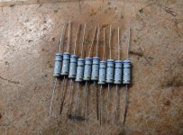
Also I bought some new 0.68Ohm resistors and all of them check about 0.91 Ohms or higher which is strange. Although that is what R10 is reporting so is it a coincidence?
resistor sm.jpg
 
Last edited:
I don't know if either of these will help you, I have two Mitsumi/Newtronics D509 drives. One is a V0 and the other is V3. The V0 has a big funky Sankyo servo motor for the heads mounted to the bottom side of the drive. the V3 has a, more normal for later drives, servo sticking out the back of the drive. Both are 1.4/360, but perhaps some usable parts swap?
 
So this is starting to really get to me.

What else could make this drive operate this way?
As per post #35

Have you put the scope on the output of the tach generator yet so as to compare that with a working board or another working motor ?

It sounds like, with nearly everything checked & replaced now on the pcb, that likely pcb (IC & parts there) are probably working ok. That would mean, as it is running fast, the IC must not be receiving a proper tach signal.

As noted, even if the Tach coil has normal resistance on its two terminals, its output could still be defective for a couple of reasons for example, one other reason, if one side of the coil or part of it had shorted to the motor body. It really needs the scope check, to look at the signal arriving at the IC input and preferably a comparison with another unit.
 
Back
Top