• Please review our updated Terms and Rules here

1982 Kaypro II no display

r34per

Member
Joined
Mar 1, 2021
Messages
20
I got a Kaypro II today that i've been trying to get working most of today. At first the psu plug had cracked solder joints, so I reflowed that and was able to power the system on. Now the problem is that I don't seem to get any image on the crt. I can hear the crt kick on and hear the typical whine that they make, and the a: floppy drive light comes on but that's about it. Pressing keys on the keyboard doesn't seem to do anything. I can see both the floppy drive motors spinning even with no disk inserted, and inserting a disk does nothing either. I reseated the IC's, and cleaned the legs of them too since there looked to be some gunk on them. I tried swapping to memory around to see if that would help but nothing changed unfortunately.

Is it possible there's a dead chip somewhere, and if so where should I start looking?
 
my kaypro ii failed to boot recently because tantalums on the floppy shorted. try booting it with nothing connected to psu but mainboard and crt.
 
No dice :/ it seems to be getting power fine, im reading both 12v and 5v on the dc plug to the mainboard.
 
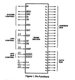
If the Drive A: LED came on it's likely that the CPU is running. But you can double check that by
verifying you have the CLOCK signal at Pin 6 of the Z80 CPU. Also check that none of Pins
16, 17, 24, 25, 26 are being held LOW = 0 VDC. If those signals are all HIGH (greater than
2.5 VDC, then I'd suggest starting with a NOP tester, created by using a known GOOD Z80 CPU.
Take the known GOOD Z80 and bend pins D0 thru D7 out enough that they do not go into the
Z80 IC socket. Then jumper each of those Pins (D0..D7) to Pin 29 of the Z80 CPU. This straps
the Z80 to Opcode 0x00 which is NOP. The address lines will increment as the CPU counts up.
You can check each address line with your O'Scope. This should allow you to check about 80%
of the computer. The Data Lines won't be checked, by the Z80 NOP tester.

Larry
 

Attachments

  • z80-1.png
    z80-1.png
    83.1 KB · Views: 7
It is possible that only the display logic is failing. When you say "inserting a disk does nothing" do you mean it display no text or messages? Or that there is no activity change? Inserting the disk and pressing RESET should cause the system to boot. After boot, there should be an idle timeout after which the drive select LED and/or motors go off. I know the newer models do that, not 100% sure about the II. But, if the LED and motors go off, you could try "blind typing" the DIR command and see if the LED/motors come back on (to perform the DIR command). If all the works, then you know to focus on the video circuitry.
 
It is possible that only the display logic is failing. When you say "inserting a disk does nothing" do you mean it display no text or messages? Or that there is no activity change? Inserting the disk and pressing RESET should cause the system to boot. After boot, there should be an idle timeout after which the drive select LED and/or motors go off. I know the newer models do that, not 100% sure about the II. But, if the LED and motors go off, you could try "blind typing" the DIR command and see if the LED/motors come back on (to perform the DIR command). If all the works, then you know to focus on the video circuitry.
Correct, I do not see any text or messages on the screen. Looks like the system does actually boot! Typing in dir does indicate drive activity, and typing in b: switches to the other floppy drive. Can't believe I didn't think to try that, lol. cpm loads so fast it looked like the drive made no attempt to read it all!

So, where should i start with troubleshooting the display logic? Like i said the crt does seem to kick on, and i hear that distinct whine from it. Adjusting the brightness does seem to work but it's hard to see since there's nothing to display.
 
Last edited:
Is the CRT filament glowing?

Do you have a working boot disk ?

The drive LED will remain on even after the diskmotor stops spinning. By (blind) typing B: (Enter) the drive LED of the B drive should come on, all of course after booting with a working boot disk in A
 
Is the CRT filament glowing?

Do you have a working boot disk ?

The drive LED will remain on even after the diskmotor stops spinning. By (blind) typing B: (Enter) the drive LED of the B drive should come on, all of course after booting with a working boot disk in A
Yes i do see the crt filament glowing. And i did make a cpm boot disk and the system does appear to boot to it. Blindly typing dir i can hear the drive reading, and switching to b: does switch the light over.
 
OK, so it sounds like you can see the video raster, when brightness is turned up? That would indicate that the video clock and counters are (mostly) working. There is no CRT controller on these older Kaypros, so it is discrete logic - that good in the sense that you don't have any custom-LSI chip that cannot be acquired except to cannibalize another Kaypro...

If you don't already have it, get a copy of http://www.bitsavers.org/pdf/kaypro/1484-F_Kaypro_Technical_Manual_Sep85.pdf. That at least gives you schematics and some other useful info. The video RAM is in the same "bank" as the ROM, and since the ROM boots the system we can assume the basic bank select logic is working. Perhaps writing to video RAM is not working, so none of the characters ever get to the video RAM. Then probably work you way outward. It's always possible that the character generator ROM is "blown", too. Maybe that is easier to check first, if you've got an EPROM programmer that can read it (or a "known good" replacement).
I do indeed have an eeprom programmer. I just tried reading it in xgpro and the ascii is just '.'s but there looks to be values there. Comparing it with a character rom image i found online they look to be about the same. I tried reading the bios as well(81-149) and i was able to successfully read it. It's one of those UV erasable chip, 27160. Just to be on the safe side, can i reflash it with my tl866ii? Are there more modern equivalents for the 27160?

@ldkraemer, there was some sort of film on a few of the IC legs. I pulled them out and cleaned it off and resocketed them. It was also on some connectors which i also cleaned off
 
Last edited:
I don't have much experience with modern eprom programmers, but I have heard that some of the legacy chips require higher programming voltages that things like the tl866ii can't produce. I'm thinking that's things like 1702's, though, so maybe it will work. I believe there are also modern EEPROM (flash) devices that are pin-compatible with the target circuit (not compatible with old programmers).

The character generator ROM is inverted (data), so anything that prevents it from getting selected (or erased it) is likely to show blanks on the screen. But, you say the ROM has data so it is probably not erased/faded. You might need to check the /CS (/G) pin for a "likely signal". Then there's the 74LS174 that latches the dot-pattern from the ROM, then the 74S151 that multiplexes that into the dot stream for the video. And possibly even the 74LS00 used to invert/buffer that dot stream. I guess you can work that chain in any order, maybe check that you're getting "reasonable video" output first, and trace backward. That's assuming you've got an oscilloscope.
 
I don't have an oscilloscope unfortunately, what would be the best way sans one?
 
I don't have any good ideas without an oscilloscope. Some modern multi-meters have a frequency setting, but I'm not sure if that will help. I'm not sure what frequency it will display for something as complex as a video signal - although it would probably give you a good idea if there is no signal at all. You may have to start swapping parts, looking at associated circuitry related to driving the ROM (U43) /CS and /OE signals, the latch (U42) clock, and the mux (U41) select signals, plus those parts themselves and the video output inverter/buffer U15.
 
Turns out XGpro has the ability to test 74x ic's. I pulled the ones you mentioned and they came out good. Also, I just noticed something on the computer when i turn it on- Very briefly a block of garbled characters appear in the lower half of the screen and then disappear. Pressing the reset button and watching the screen doesn't replicate this, only when flipping the power switch.
 
On a budget, I use this most the time testing equipment, cant beat it for the price... Ya its only 24mhz but should be more then capable for your needs. And a steal for 10 bux! Downside is the slow boat ride from china, but im sure there are others on ebay with american sellers.


While the software isnt the greatest, it gets the job done. If you perfer linux software, sparkfun has a copy of the same logic analyzer, with a link to software.


It sure beats a dumb logic probe thats for sure!
 
Last edited:
You do have the correct boot disk for your Kaypro ? I can imagine if you have a boot disk for the newer types with the CRT controller chip you won't get any picture as they work completely different.
 
Not to hijack, but does anyone have a recommendation on a replacement keyboard jack for a Kaypro II? For the keyboard plug, rather than the rear of the computer.
 
Turns out XGpro has the ability to test 74x ic's. I pulled the ones you mentioned and they came out good. Also, I just noticed something on the computer when i turn it on- Very briefly a block of garbled characters appear in the lower half of the screen and then disappear. Pressing the reset button and watching the screen doesn't replicate this, only when flipping the power switch.
The garbage might not be anything wrong. The screen is cleared by the CPU running the ROM code, and it takes a finite amount of time. Unlike the newer versions with the CRT controller chip, there is no "enable display" and so it's possible that the video refresh circuitry completes one or two refresh cycles before the CPU has completely cleared the video RAM. The slow phosphor on the Kaypro CRTs makes it entirely possible you can see those initial refresh cycles. RESET would not re-introduce garbage into the RAM, only a power-cycle would.

Some other possible causes are bad solder joints or bad sockets, of even possible failed/damaged traces on the PCB. But you probably are going to need some better diagnostic tool, like a logic analyzer or oscilloscope, to track down where the problem is.
Oh gotcha, that makes sense. I did check the bottom of the board for any cracked joints and everything looks good to me, no cracked joints or cut traces. I do have a logic analyzer, but it's those old ones that need the right cartridge i think. Been meaning to pick up an oscilloscope though.I did notice the 2114 srams get quite warm in a short amount of time, after leaving it on for around 10 minutes they're almost to 50c, most other chips are in the 30's.

Also, it looks like something is trying to be displayed. I made a new cp/m image making sure I got the right image and i see point of light in the lower left. When i type random text then mash enter it looks like that point of light moves. it's hard to explain so i attached a video. The first thing i typed was 'DIR', i was a little vague about that.


also @bifo86 i used a regular phone handset cable on my kaypro 2 and it seems to work fine. I read that depending on the quality it may not always work quite right but it's wired the same
 
Last edited:
Back
Top