• Please review our updated Terms and Rules here

50 Pin Floppy to 34 Pin Floppy Converter Board

Why bother with the HCT123? Are you pin-constrained? An ATMEGA-8 MCU in a 28 pin PDIP can have as many as 23 i/Os.

You 300 RPM Teac GFR has jumpers to alter the drive speed. If you're using it as a sub for an 8", you do want it to spin at 360RPM.
 
I plan to use the board the other way around. From CP/M with PC8477 and 34pin connector to 8" inch drive(s). Therefore the TG43 and Atmel. But it should be usable in both directions.

Regarding TEAC - it is jumpered identically to the faster spinning one. I think it has damage to spindle motor control electronic. Lets ignore it now. I am not yet sure about HCT123. I wanted something for quick diagnostic of INDEX pulses, Track 0 signal etc. because of non working TEAC drive. The question is if anybody but me would ever find it useful. Probably not.

PIC16 - I do not know the beast. ATMEGA8 - I can not do it in assembler, only in C, and 15 pins of little Atmel seem to be fine. When I have something ready I will post.
 
PIC16 - I do not know the beast. ATMEGA8 - I can not do it in assembler, only in C, and 15 pins of little Atmel seem to be fine. When I have something ready I will post.

I was just thinking aloud--the mega8 has a very simple instruction set and is easy to do in assembly. I was thinking of why stretch the index pulse with a one-shot if you've got an MCU with timers. And then, I said, well, you can even drive the LED with a bi-color one and indicate if the spindle speed is 360 RPM (or 300) +/-10% or if it's out of spec.

I haven't looked at your code, but I assume that since not all 5.25" drives have a READY line, you're using a timer or a pair of one-shots to synthesize that also.
 

Sorry for shaky video. The drive is stopped in the beginning, then started. Stepping of the drive can be heard when track number changes. In the end the drive stops, so the rpm value disappears again. It took me few days to make this wire mess on my table and write code for AT89C2051. As a proof of concept it looks like it is doable. I am at little more than 800 bytes so far, so even Atmel with as little as 1k of Flash should be sufficient. It is almost finished, still have to implement TR43 signal, calibrate to zero at Track0 signal and check Rpm value. Because the 3.5" should show 360rpm. I only tested it with 3.5" TEAC. Code is in attachment.

Chuck could you please elaborate a little on READY line? I would like to start drawing schematics. A pair of one-shots for READY signal is interesting. Timer1 of AT89C2051 is not used so far, so that could be an option too.

EDIT: RPM value is actually correct, 3.5" drives have always 300rpm
 

Attachments

  • FDD8.zip
    5.7 KB · Views: 1
Last edited:
In another thread I found this.

The whole rationale behind the READY signal in the 8272/765 is that it's an 8" controller, where the drive spindles are always spinning. So READY really indicated that a disk was inserted in the drive. This was used by the "polling" mode of the FDC to periodically select each of 4 possible drives and generate an interrupt should the status change. To disable this, not only is READY tied active, but the 765 drive select outputs are no-connects, such that polling doesn't do anything.

So how does the PC determine that a drive isn't ready? Easy--by attaching a deadman timer to every operation. If an operation hasn't completed in about a second, the 765 can assumed to be hung, and a RESET signal is issued, and the FDC is respecified.

Note that the 5170 uses the 765/8272 but supports DISK CHANGED as well. This is done, like unit select and motor control, by external logic. Basically, a disk changed status is asserted by a drive when a disk is inserted or removed. The status is reset by moving the heads (a "step in" followed by a "step out" is sufficient). The treatment of the status is up to the drive software--usually in the case of 360K and 720K drives, it's ignored--and for 1.2M and 1.44M, it's treated as an error and passed up to the calling program.

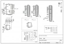
And there is a chart here, is it correct?
https://www.msx.org/forum/msx-talk/hardware/difference-between-disk-change-and-ready

Would a one shot periodically prolonged with INDEX pulses so that that it never goes down be enough for READY? As soon as INDEX stops one shot would also go down. One half of 74123 is still free. Can READY not be tied to VCC? Sorry I still do not overlook whole point here.

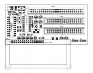
Schematics is in progress, DENSEL, READY are not yet finished. Last question can four drives be connected like that?

View attachment 31668View attachment 31669
 

Attachments

  • sch.jpg
    sch.jpg
    92.6 KB · Views: 2
  • pcb.jpg
    pcb.jpg
    64.9 KB · Views: 2
Last edited:
Yes, that's the basic idea behind READY. Of course, you don't want a one-shot to trigger and signal READY before the drive is up to speed, so you should use two one-shots to avoid a false indication. But if you're clocking RPM anyway, why bother with one-shots? You've got the information that the drive is up to speed, so that implies READY, no?

But again, going to what I said earlier, the IBM PC family doesn't use READY. However, there are some drives that block INDEX until a drive comes up to speed, so there's a READY mechanism that way. I have an old Micropolis 5.25" drive that blocks index during a buffered seek for the same reason.

MS-DOS without the DISK CHANGED line (i.e. old 360K/720K drives) could get into the state where the directory information didn't match the disk in the drive and really get you into trouble. There used to be numerous citations in the KB about this. When 1.2M and 1.44M drives came into the picture, the problem went away because the drive could tell the OS when to refresh its copy of the drive data.
 
There are two problems with Atmel driven READY. If I want four drives like in schematics I have no more pins. And I when I was testing RPM I observed, that when drive is stepping heavily (e.g big file assembly in CP/M) the RPM value halved sometimes. I did not have LEDs anymore at that time, but that tells me, when stepping, there is no INDEX pulse probably (one missing from time to time to be exact). And I too had the impression of READY signal the delayed INDEX way with TEAC 3.5" and 5.25" drives I attached. Now it is all disassembled again. I will think about two one shots and other.
 
Back
Top