• Please review our updated Terms and Rules here
  • From now on we will require that a prefix is set for any items in the sales area. We have created regions and locations for this. We also require that you select a delivery option before posting your listing. This will hopefully help us streamline the things that get listed for sales here and help local people better advertise their items, especially for local only sales. New sales rules are also coming, so stay tuned.

8-bit ISA VGA adapter for IBM PC 5150

Yes as per the manual:
J7: "short" ( don't have a j6)
J8: "open"
J9: "all short"
I goofed. According to the manual, J6 is only in the 8900D.

Whilst searching through my stash of parts today i found a 16-bit card with a Trident TVGA9000i-1 chip, I tested it in my 5150 and 5160 and it didn't work, both machines gave out one long and two short beeps,
To confirm my understanding, I just now re-read part of the source code for the IBM 5150 BIOS. The only time that the BIOS jumps into the code that may issue the error code of 'one long beep followed by two short beeps' is when the motherboard video switches are set to MDA or CGA.

When the 5150 motherboard switches are set for EGA/VGA, then error indication is issued by the BIOS expansion ROM on the video card. For example, IBM EGA cards issue a 'one long beep followed by three short beeps' error code. It is possible that your Trident TVGA9000i card issues the error code of 'one long beep followed by two short beeps', but I think it more likely that you forgot to change the 5150 motherboard switches to EGA/VGA.

Do you remember setting the 5150 motherboard switches to EGA/VGA ?
 
Yes SW1 5=ON, 6=ON, I even toggled the switches on and off several times on both machines thinking they might be a bit sticky but made no difference, Both machines still gave out 1 long and 2 short beeps, The 3 other cards i tried all worked in my 5160 but i didn't try them in my 5150, I will try them in the 5150 a bit later.

EDIT: I have tested the 3 other cards in my 5150 and only 2 of them work in the 5150 which are the Cirrus Logic and ACU Mos, The OTI067 does not work in my 5150 for some reason.


Do you remember setting the 5150 motherboard switches to EGA/VGA ?
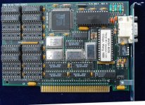
 
Last edited:
I have a VGA card now, Trident TVGA 9000I, set for 8-bit (now at least), buuuuuut, where do i set the system to use EGA/VGA, it came with an IBM MDA so I'm expecting it would be setup for that now, don't know where the switches would be or what they sohuld be set to though.
I found two DIP Switches (under the MFM and floppy cables, so it its those I may need to disconnect those to reach them), but even if its one of those switches (there two sets) I still don't know which should be set to what.
(one pretty much center behind the floppy drive the other on the left edge of the floppy)

reading back a bit, on those switches 5 and 6 are ON, and I did try but the system did give an error, 1 long 2 short so it seems I need other switches, but so far I don't see any.
 
assuming I need the switches closest to the PSU, its setup for no Co Processor, 640kb, EGA/VGA, 1 FDD.
which would be correct, but I still do get the error of 1 long beep and 2 short.


update: error is gone when I plugin the MDA card again
 
Last edited:
assuming I need the switches closest to the PSU, its setup for no Co Processor, 640kb, EGA/VGA, 1 FDD.
which would be correct, but I still do get the error of 1 long beep and 2 short.


update: error is gone when I plugin the MDA card again
Nope, the block closest to the PSU is for memory options. The other block, near the center of the board is the one you want to fool with.
 
the one closes to the ISA slots then? around the same position as the CPU (but more towards the floppy).
ok, then I have 1 = ON, 2 = OFF, 3 = ON, 4 = ON, 5 = ON, 6 = ON, 7 = ON, 8 = OFF
however, from what I get, 1 should be OFF for normal operation, 2 should only be off is a co-processor is installed (which AFAIKO isn't), 3 and 4 ON means 256Kb RAM, but if the expansion card should be included in this its more, 5 and 6 are ON so should be set for EGA/VGA, which is weird given the error implies its trying to find an MDA/CGA card, 7 on and 8 off should mean 3 floppy drives, which is wrong since there is only one floppy and a hard disk (the controller does support a external floppy as well, not sure if thats important if it isn't connected?)

edit:
and I seem to have 512Kb extra on the expansion card, that is two banks with KM41256-15 chips which I found are apparently 256k x 1 bit
so together with 256k onboard that means 768k RAM total, but as that's more then the DIP switch can be set for, either the system can't handle this much, or the switch only means onboard (and while the 5150 doesn't support 640k onboard, I'm guessing the XT does?)
 
Last edited:
Switches 7 and 8 should be ON, ON for one floppy and off, ON for two floppies.

FWIW, the XT doesn't have the second switch block for the memory options, only the PC has that. Try it without the memory card and set the switches for 256K.
(ON, off, off, ON, ON)
 
I have one floppy, so that would be ON, OFF, OFF, ON, ON, OFF, OFF right?

however, I noticed something, I've only ever seen sliding switches for DIP switches, these are lever switches, e.g. the side that's pressed down is likely the side its set for, meaning it was OFF, ON, OFF, OFF, OFF, OFF, OFF, ON.
yet, I don't see a memory setting that used OFF for both 3 and 4, the floppy's are then set to 2, but its also set to MDA/CGA, not EGA/VGA as I though it was.
I'll give it a try with the memory upgrade card off, as 1 = ON, 2 = OFF, 3 = ON, 4 = ON, 5 = ON, 6 = ON, 7 = ON, 8 = ON
so BIOS POST normal, no Co-Processor, 256k (onboard) RAM, EGA/VGA and 1 floppy drive.

using that, there is no error tone, but I also don't get signal on the display.


edit:
btw, reading the link malc gave,
The SW2 switches are set to the total amount of RAM fitted in the 5150 (that is, RAM on motherboard + RAM on expansion cards).
, doesn't that mean removing the expansion card means those settings are now wrong?
 
Last edited:
I have one floppy, so that would be ON, OFF, OFF, ON, ON, OFF, OFF right?
There are EIGHT switches. When you only list seven switch positions how are we to know what you are trying to tell us? You are only making a confusing situation more difficult to figure out. BTW, one floppy (to repeat my earlier post to you) = ON, ON for switches 7 and 8.


however, I noticed something, I've only ever seen sliding switches for DIP switches, these are lever switches, e.g. the side that's pressed down is likely the side its set for, meaning it was OFF, ON, OFF, OFF, OFF, OFF, OFF, ON. yet, I don't see a memory setting that used OFF for both 3 and 4,
I have... better go back and take another look at your source. Off, off = Four banks of memory.
 
There are EIGHT switches. When you only list seven switch positions how are we to know what you are trying to tell us? You are only making a confusing situation more difficult to figure out. BTW, one floppy (to repeat my earlier post to you) = ON, ON for switches 7 and 8.
that could have been a little less harsh, as for what I meant, same as you did when you listed 5 but with addition (although incorrect) of the values for the floppy drive.
the one that's missing, you left out as well:
FWIW, the XT doesn't have the second switch block for the memory options, only the PC has that. Try it without the memory card and set the switches for 256K.
(ON, off, off, ON, ON)
not trying to be offensive but I find it at the least strange to make a response like that while you also didn't list all switches.


I have... better go back and take another look at your source. Off, off = Four banks of memory.
my source was that one Jorg gave, although I do also see it now as well there.


I can guarantee this in general is at least as confusing for me as that one thing may have been for you, I have no experience at all working with systems like this, and I have never had to setup the hardware on a system with jumpers and/or DIP switches.

now looking at the site malc linked, if I understand it correctly, what I need for my unit is 1 = OFF, 2 = ON, 3 = OFF, 4 = OFF, 5 = ON, 6 = ON, 7 = ON and 8 = ON.
for one or more floppy drives installed, no math co-processor, memory banks 0/1/2/3 all populated, video card type VGA/EGA/PGA, 1 floppy drive installed.
 
not trying to be offensive but I find it at the least strange to make a response like that while you also didn't list all switches.
The reason I only listed five is quite apparent:


  • Switches 6, 7, 8
  • Always off

Since there is *no* option here I didn't feel the need to be redundant and state something that should be immediately obvious to everyone who had read the manual. :)
 
Yes that's correct for SW1, Check SW2 settings are correct for the amount of memory the machine has and also check you have the 3rd rev bios fitted: Chip U33 has "1501476" printed on it.

now looking at the site malc linked, if I understand it correctly, what I need for my unit is 1 = OFF, 2 = ON, 3 = OFF, 4 = OFF, 5 = ON, 6 = ON, 7 = ON and 8 = ON.
for one or more floppy drives installed, no math co-processor, memory banks 0/1/2/3 all populated, video card type VGA/EGA/PGA, 1 floppy drive installed.
 
and according to the guide to operation that would be SW2 as 1 = ON, 2 = OFF, 3 = OFF, 4 = ON, 5 = ON, 6 = OFF, 7 = OFF, 8 = OFF, for 256k with the multifunctional controller removed.


yet that still gives no signal to the display and no errors.
I also don't see a light on the floppy drive or the HD though, although I'm not certain either of them works.
 
I also don't see a light on the floppy drive or the HD though, although I'm not certain either of them works.
You are going about this all wrong. You can not use components of unknown condition to test another situation. Everything *must* be in known working condition in order to test or setup another component. If you work with multiple variables you will never come up with a valid result. Only one variable is allowed per experiment. Anything else is nothing more than an exercise in futility.
 
If you got the same card i have here i doubt you'll get anything on the display, Mine will only work in a 286 > box as i only recently found and tested it, As you're not getting anything from the speaker and no floppy / HD activity and without any known working parts it's going to be a difficult task and may not be worth it in the long run.

yet that still gives no signal to the display and no errors.
I also don't see a light on the floppy drive or the HD though, although I'm not certain either of them works.
 
Back
Top